DISPLAY PROPERTIES
In this chapter you will learn about the display properties that can be configured.
GENERAL
The General section allows you to edit common data such as Device Name and Device Host.
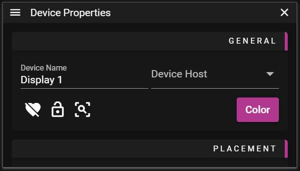
- Device Name can be set to anything you like. This name is shown in the Stage window when you are in Display Edit Mode.
- Device Host is used to set the node on which the display content will be rendered.
- Heart button is used to toggle the activate or deactivate the display.
- Lock button is used to toggle the possibility to edit the display.
- Frame button is used to change the scale in Stage so the selected display(s) are in focus.
- Color button is used to change the frame color of the display. Use it to make it easier to find specific displays.
- The color is also shown in the Devices Window.
In order to see any output from a display on a monitor etc you need to enable it. To enable a display you need to:
- Select the display.
- Make sure you are in Display Edit Mode otherwise you cannot select displays.
- Assign it to a node by setting the Device Host.
- Locate and click the heart icon located in the General section.
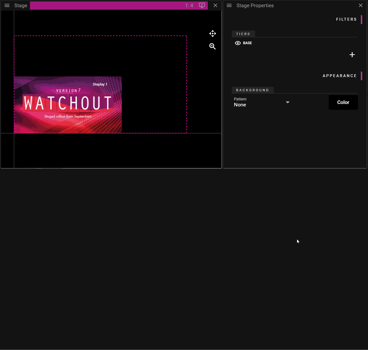
PLACEMENT
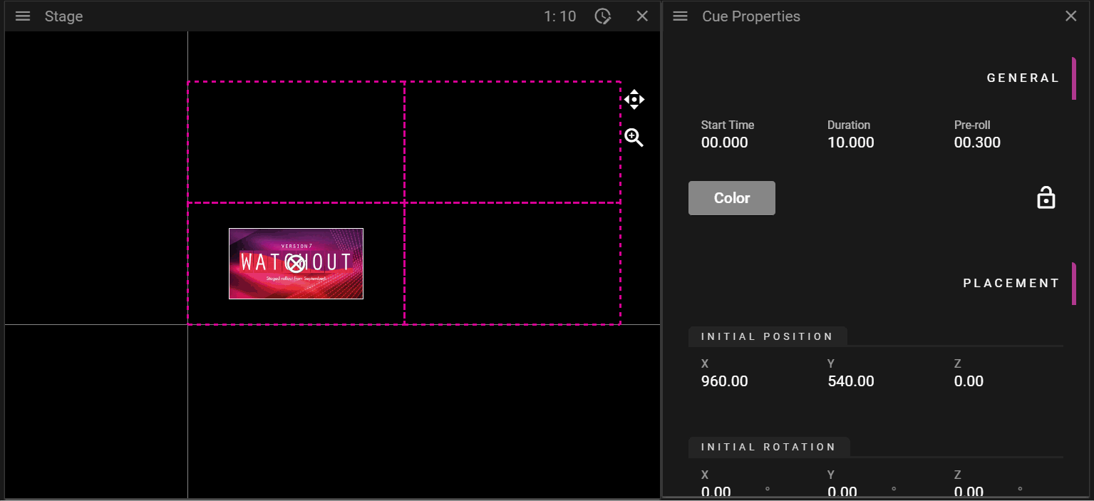
The Placement section allows you to edit data related to the location of the display in the Stage window.
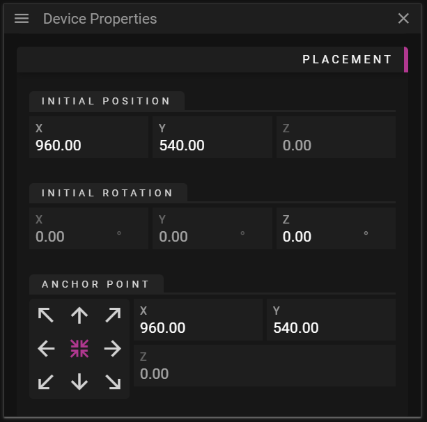
- Initial Position can be changed to edit the position of the display.
- Initial Rotation can be changed to rotate the display counterclockwise around the anchor point.
- Anchor Point defines the origin of the display and it also defines the point around which the display is rotated.
- The anchor widget, with arrows, can be used to move the anchor point to a specific corner, edge or the center of the display.
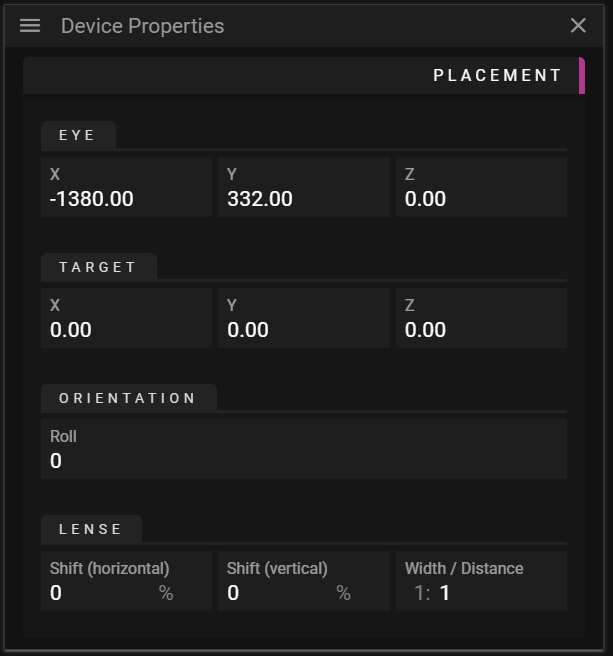
- Projector specific settings:
- Eye defines the point where the projector is located.
- Target defines the target point of the projector when there is no lense shifting.
- Orientation defines the rotation around the direction vector.
- Lense Shift can be used to change where the projector displays its image without changing the position of the projector.
- Width / Distance Ratio can be used to change the shape of the projection frustum.
- Note: During the calibration step when doing 3D Mapping a number of the projector settings above are modified.
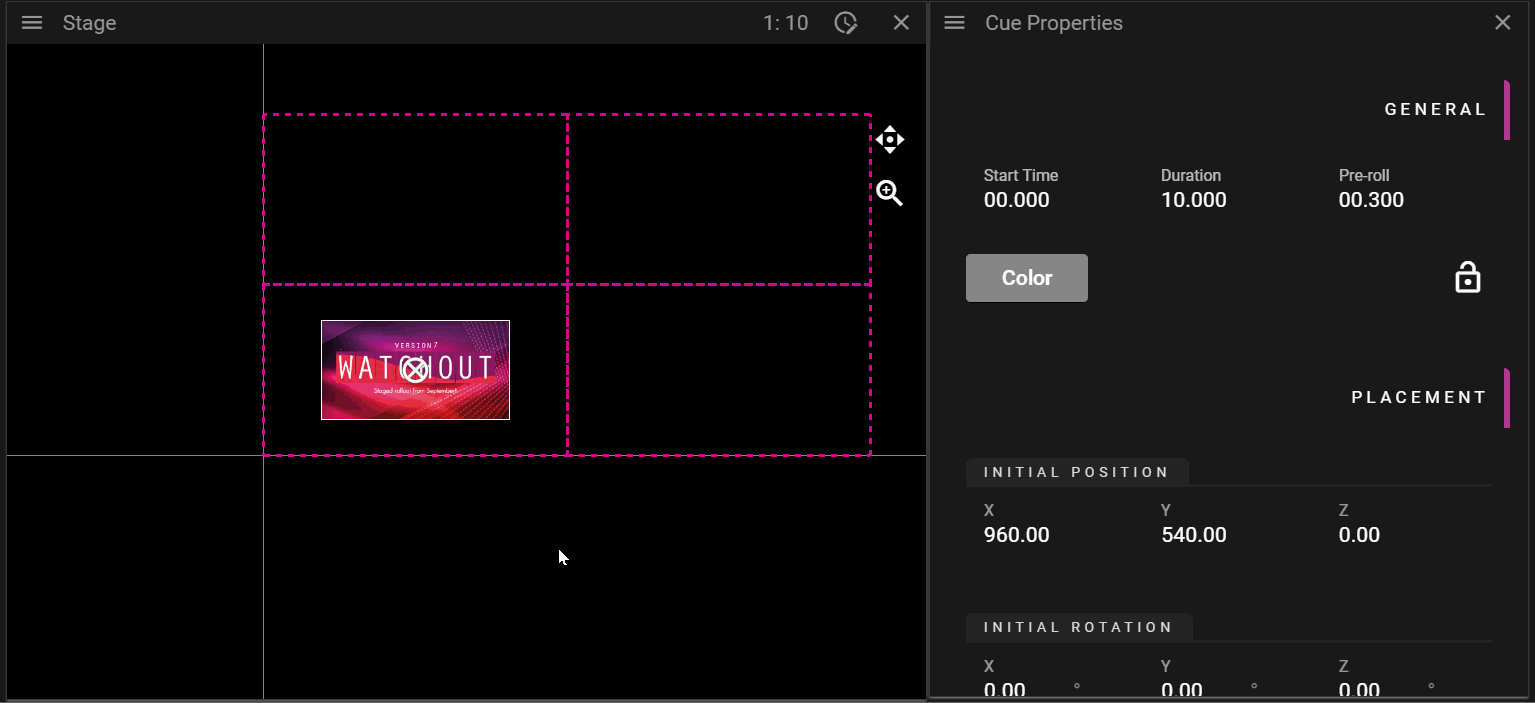
In the following example the anchor and rotation of a display is being edited:
PRESENTATION
The Presentation section allows you to edit the tiers of the display.
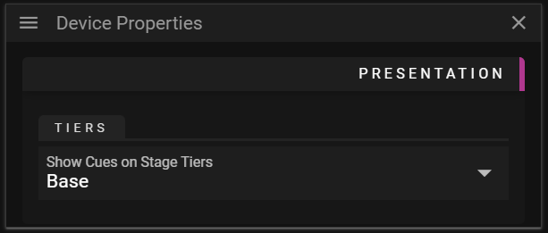
- Tiers
- Show Cues on Stage Tiers can be changed to make the display only render cues that belong to a specific tier.
OUTPUT
The Output section allows you to edit settings related to rendering the referred cues to a display device.
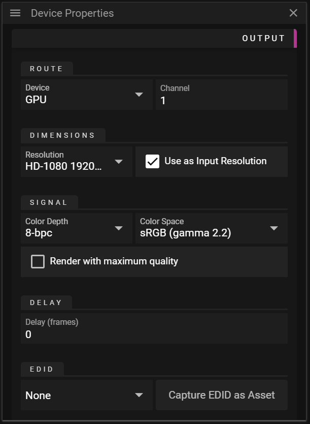
- Route
- Device defines the target buffer for the display. It can be set to GPU, SDI, NDI® and Virtual.
- Channel defines the display device to render the display content to.
- Dimensions
- Resolution is used to define the wanted output resolution. That is the resolution of the buffer to which WATCHOUT renders the cues.
- Use as Input Resolution can be toggled off to use a custom resolution for the display in Stage.
- Signal
- Color Depth defines the number bits used per color channel/component.
- Color Space defines the color space to use for rendering.
- Delay
- Delay frames allows you to delay the rendering of a display. This can be useful to make different displays play exactly in sync.
- EDID
- The drop-down will show all EDID assets available in the Asset Manager currently in use.
- EDID files can be added to the Asset Manager just like any other asset.
- Capture EDID as Asset button captures the current EDID information as an asset and uploads it to the Asset Manager.
- This is only supported on NVIDIA Quadro-based GPUs.
- The drop-down will show all EDID assets available in the Asset Manager currently in use.
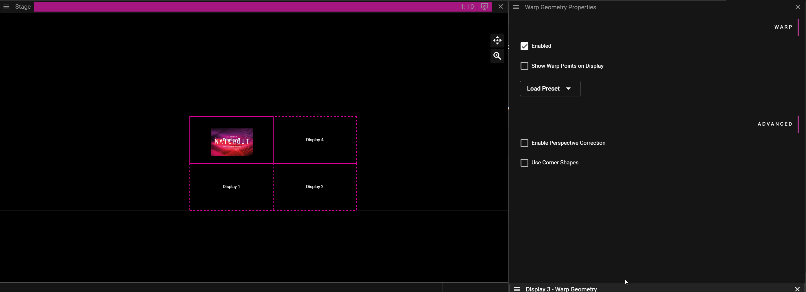
WARP
Warping can be useful to make the display output follow an irregular surface, like a curved wall.
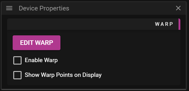
- Enabled toggles warping on or off.
- Show Warp Points on Display toggles the rendering of warp points on or off.
- Edit button opens a window allowing you to modify the warp mesh onto which cues are rendered.
NOTE: You can use a XBox type of controller to adjust the warp points.
For more information look in Appendices / XBox Controller
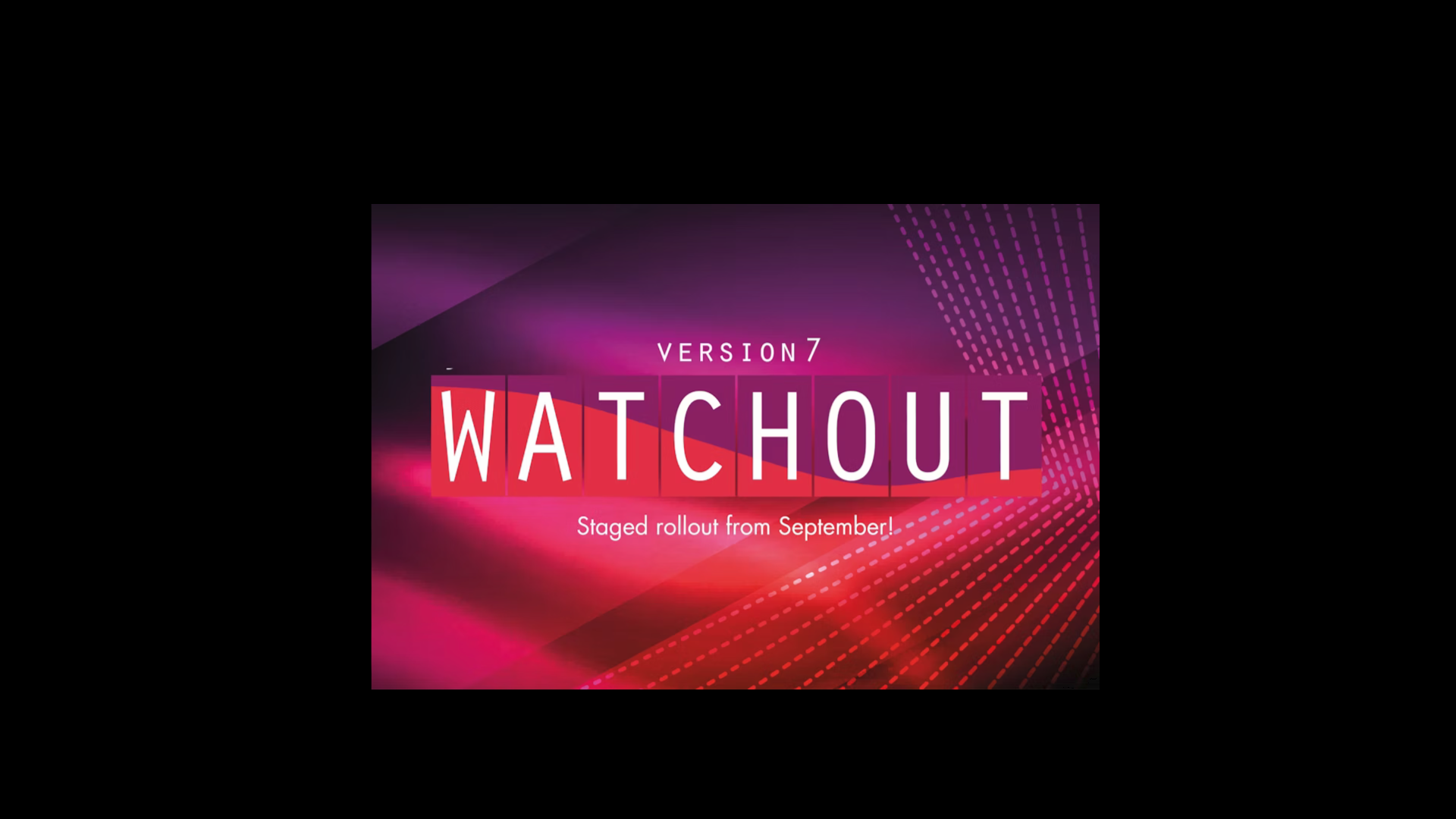
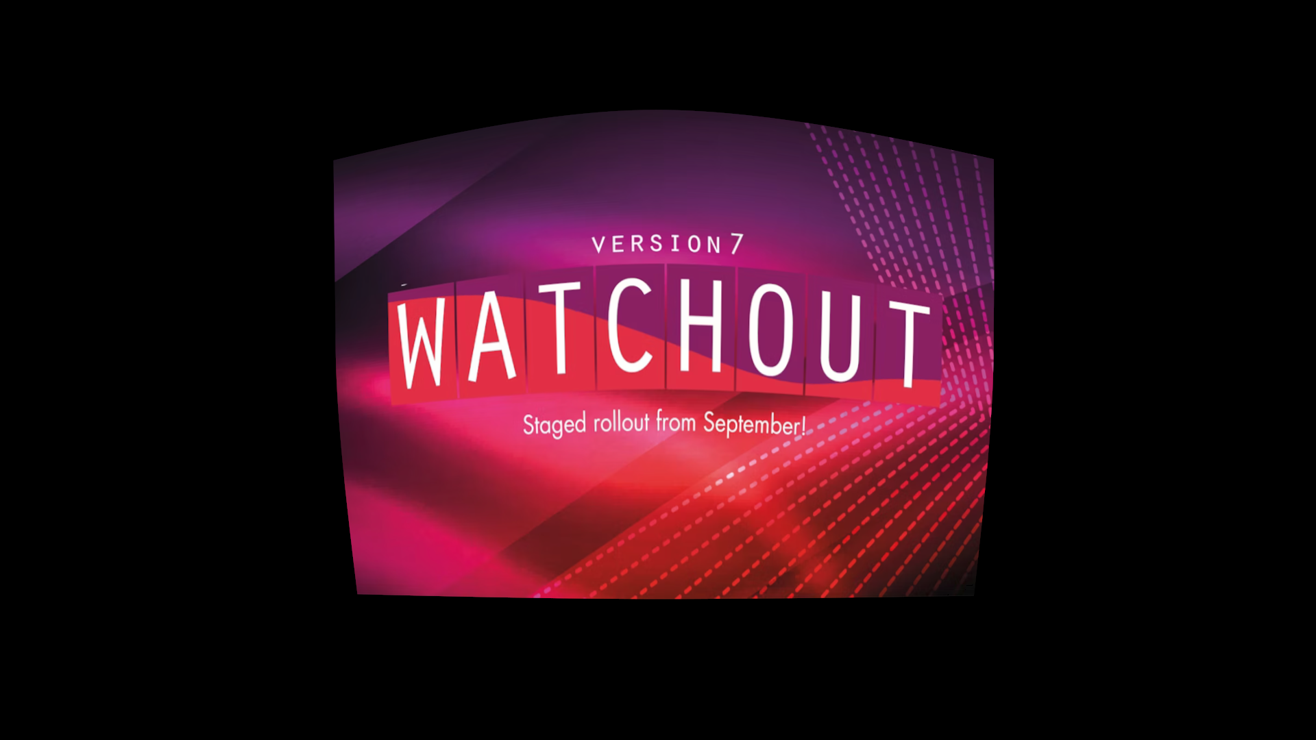
Below we edit the warp mesh to change how the output is rendered:
Before:
After:
MASK
Masking can be useful in situations where you want to block parts of the display output. For instance, if you have a pillar between a projector and the projection surface you might want to avoid displaying content on the pillar. This can be achieved by using mask(s).
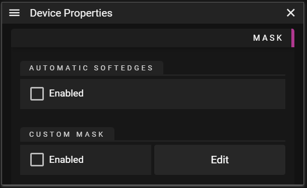
- Automatic Soft Edges allows you to get automatic blending in the areas where displays overlap.
- Enable toggles automatic soft edges on or off.
- Only displays that have this feature enabled will contribute to the soft edge solution.
- It does not matter if the actual display is enabled or not.
- Enable toggles automatic soft edges on or off.
- Custom Mask can be used to block render display outputs for certain pixels.
- Enable toggles custom masking on or off.
- Edit button opens a window allowing you to create and modify mask surfaces.
- The mask layers are local to this display.
DISPLAY MASK EDITOR
The display mask editor allows you to add and edit multiple mask surfaces to your display to limit the areas where the display renders pixels. The Display Mask Editor window shows what the display is currently rendering in Stage. This is to simplify positioning the masks you want to use for your display.
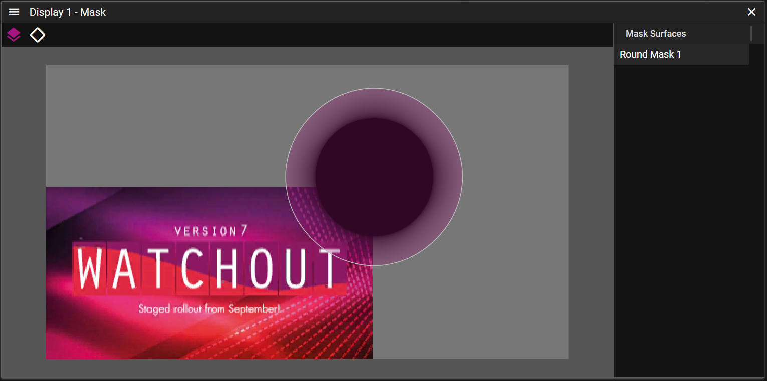
WATCHOUT provides a number of predefined mask surfaces that can be added from the Display Mask Editor menu or by right-clicking anywhere in the Display Mask Editor window.
Once a mask has been added it will be shown in the right column of the Display Mask Editor named Mask Surfaces. It is possible to select multiple masks and edit them together. To do so you may either select them by clicking on their name in the Mask Surfaces column, or you may click or drag select them directly in the mask window.
There are two edit modes for masks:
- Edit Surfaces which allows you to edit one or multiple mask surfaces.
- You can activate this mode by clicking the surface icon found in the upper left corner of the Display Mask Editor.
- You may move, stretch or rotate one or multiple mask surfaces by interacting with the control points that are shown once one surfaces have been selected.
- Select one or more mask surfaces by clicking on them in the Display Mask Editor window. Note that you can hold control or shift button to modify the select operation. You can also select one or multiple masks with a drag select operation or click on the mask surface you want to edit in the Mask Surface section found on the right of the Display Mask Editor window.
- You may also change the name of the mask surface to better convey the type of masking it is used for.
- Edit Points which allows you to edit one or multiple mask surface points.
- You can activate this mode by either clicking the unfilled surface icon found in the upper left corner of the Display Mask Editor or by double-clicking on a mask surface.
- You may edit one or multiple points by selecting them.
- Select one or more points by clicking on them in the Display Mask Editor window. Note that you can hold control or shift to modify the select operation.
- You can read more about the possible edit operations for points in the Mask Point Properties section.
- Add Mask Surface allows you to add a mask surface from a list of predefined surfaces.
Here is a quick demonstration of how to setup masks for your display:
MASK POINT PROPERTIES
The Mask Point Properties can be used to fine-tune a mask. You can activate it by selecting one or more points when you are in the edit point mode of the Display Mask Editor.
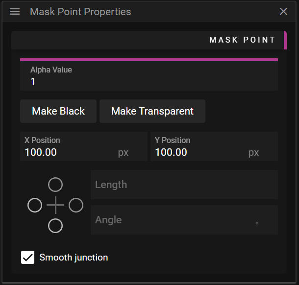
- Alpha Value allows you to define the alpha value for a specific point.
- If alpha is set to 1 it is completely opaque; if alpha is set to 0 is completely transparent.
- Make Black button is a shortcut for setting the alpha value to 1, making the point completely opaque.
- Make Transparent button is a shortcut for setting the alpha value to 0, making the point completely transparent.
- X Position defines the position along the x-axis in pixels, relative to the lower left corner of the display.
- Y Position defines the position along the y-axis in pixels, relative to the lower left corner of the display.
- Control Point Handle widget can be used to select and edit control point handles.
- Length defines the distance in pixels from the control point to the control point handle.
- Angle defines the counterclockwise angle between the control point and the control point handle.
- For instance, if the angle is 0 the point will be located along the local x-axis for the control point.
- Smooth Junction can be toggled on or off to link or unlink the bezier control point handles.
- If it is activated it means that the control point handle on the opposite side (of the handle being edited) will also be affected by edit the operation, in order to maintain a smooth curve.
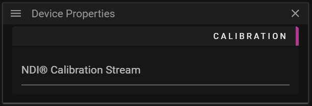
CALIBRATION
Set a NDI® Calibration Stream for the auto calibration system to take over the display. The name of the NDI® stream is given by the auto calibration software.
Assume we want to calibrate two projectors so they produce a continuous image. An auto calibration software then produces a test pattern that is outputted by the two projectors and analyzed by a camera. The auto calibration then makes the necessary changes to align the two projectors so they form a continuous image.
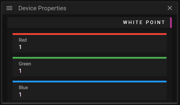
WHITE POINT
The white point allows you to define what color in the output should be considered as white.
TEST PATTERN
This property group contains the possibility to change the output of the display to a specific pattern. This can for instance be useful when working with multiple overlapping display devices.
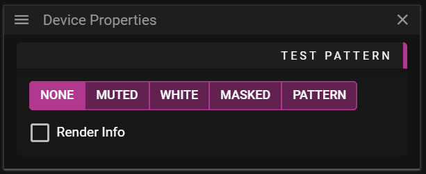
The available patterns are:
- None, outputs the cues associated with the display.
- Muted, outputs nothing for the display even if it is active.
- White, outputs white color.
- Masked, outputs the masks if any.
- Pattern, outputs a checker pattern.
You can also toggle Render Info on and off. This information can be helpful to identify screens if there are many outputs.