
Summary
-
WATCHOUT 7 Overview
WATCHOUT 7 is your creative playground for spectacular visual experiences! It combines powerful capabilities with an intuitive interface, letting you seamlessly scale from a single screen to massive multi-display productions. Its network-based design adapts to your workflow, whether you're meticulously planning every pixel or making last-minute magic happen.
Primary Applications
WATCHOUT 7 shines in these environments:
- Live Events & Conferences - Make jaws drop at concerts, corporate events, and product launches
- Museums & Exhibitions - Create immersive journeys across synchronized displays
- Broadcast Environments - Power dynamic video walls that pop on camera
- Theme Parks & Attractions - Deliver those "wow" moments visitors remember
- Fixed Installations - Keep lobbies and public spaces looking amazing 24/7
Key Capabilities
This guide will help you master WATCHOUT 7's toolkit:
- Timeline Wizardry - Build sophisticated sequences with precise timing and layering
- Multi-Display Magic - Synchronize and blend content across numerous outputs
- Visual Effects - Animate content with intuitive tweens and keyframes
- Show Intelligence - Create responsive shows with triggers and variables
- Asset Manager - Organize and distribute media across your network
- Live Controls - Make adjustments on the fly with confidence
- Plays Well With Others - Connect with external systems through standard protocols
Integration Options
WATCHOUT 7 connects easily with:
- Art-Net/DMX - Talk to lighting consoles and controllers
- OSC - Link with audio systems and modern interfaces
- MIDI - Use control surfaces and Show Control
- Timecode - Stay in sync with LTC
- Show Control Systems - Work with Crestron, AMX and friends
- WATCHOUT Protocols - From legacy to modern API options
About This Guide
The following chapters will take you from setup to showtime with clear, practical instructions. You'll learn everything you need to bring your creative vision to life on your new WATCHOUT 7 playground.
Ready to dive in? Let's get started!
WATCHOUT 7 QUICKSTART
This guide will help you get a basic WATCHOUT show up and running in 15 minutes.
1. INSTALLATION & SETUP
-
Download from Dataton website. You will have to fill in a form, but the download is free.
-
Install the software by following the on-screen instructions.
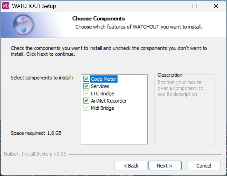
-
Start Producer and Backend by clicking
2. CREATE YOUR FIRST SHOW
-
Launch Producer
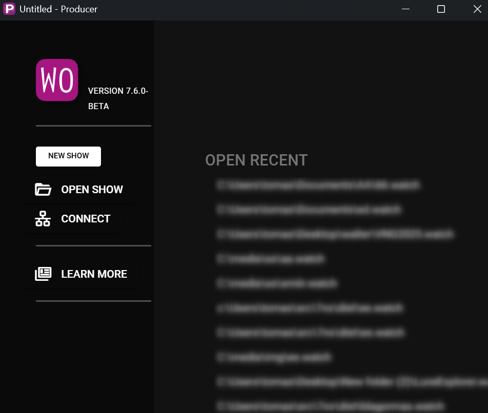
-
Create a show by clicking NEW SHOW
3. ADD CONTENT
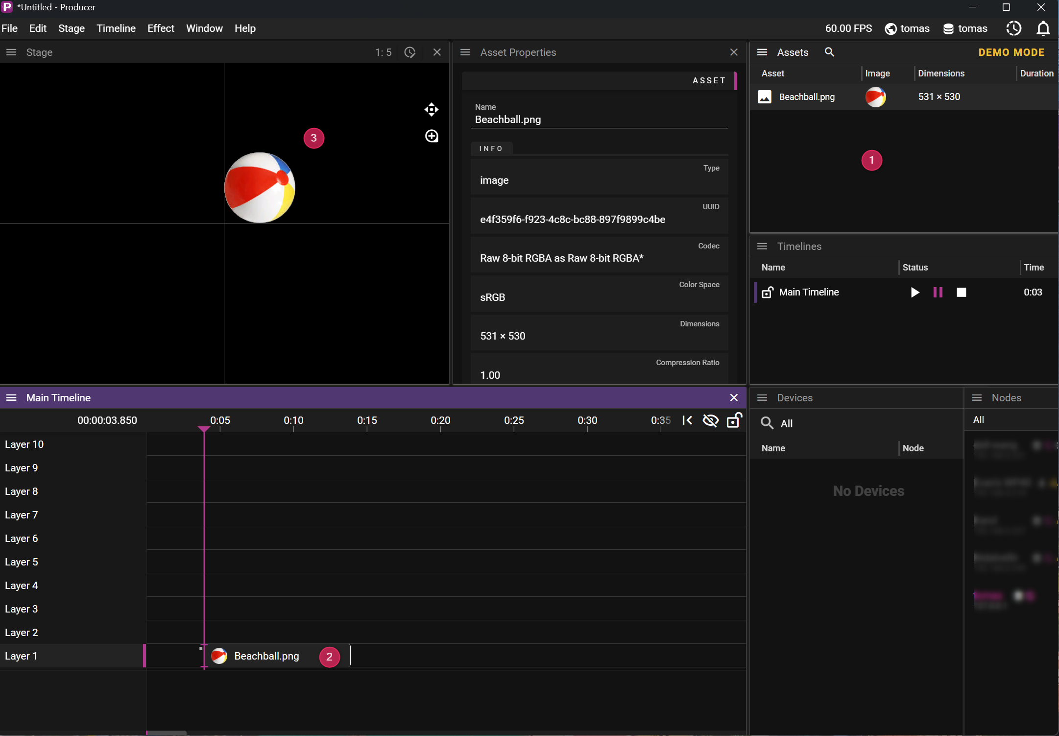
- Add an Image to Asset Manager by dropping it in Asset Window (1)
- Then drag the image to Main Timeline (2). This will make the image appear on Main Timeline and in Stage
- Now feel free to explore settings and effects by right-clicking to open context menu for (2) or (3)
4. TEST AUDIO
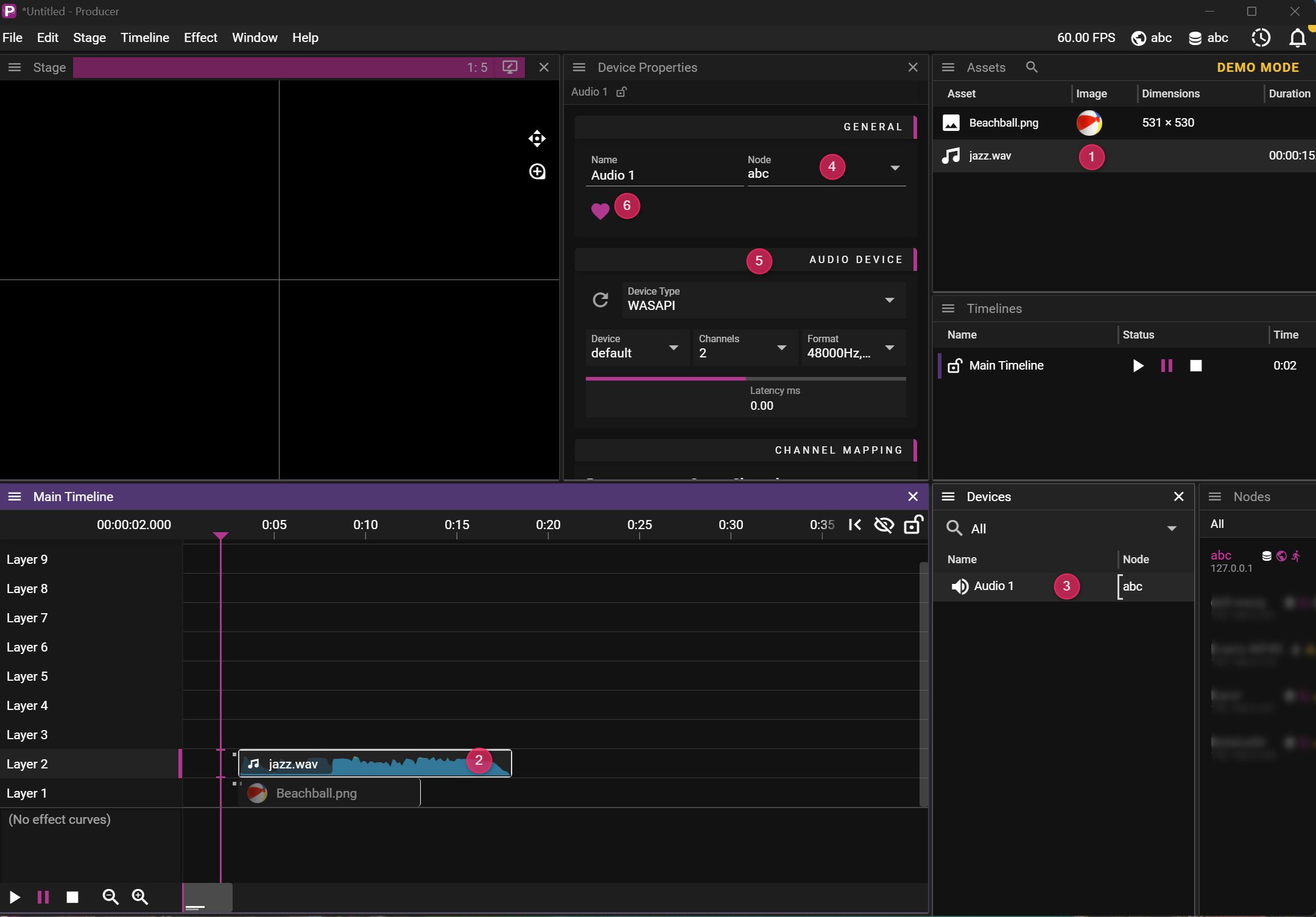
- Add Audio to Asset Manager by dropping it in Asset Window
- Drag Audio to Main Timeline Window
- Create an Audio Device from the context menu in Devices Window
- Set which node should play in Device Property Window
- Configure Audio Device in Device Property Window
- Enable Audio Device in Device Property Window
Start playing by hitting the play button in Main Timeline Window
NOTE: Property Window changes its content depending on what object you have selected. For Device Properties, select the Device in the Device Window.
5. DEPLOY TO DISPLAYS
This requires a license, but the steps are similar to adding an Audio Device:
- Create a Display in Devices Window
- Configure it in Properties Window
- Enable it in Properties Window
Start playing by hitting the play button in Main Timeline Window
6. NEXT STEPS
-
Learn more in depth:
- Explore Devices Window for display configuration
- Master Audio settings for complex sound setups
- Understand Effects to enhance your presentations
-
Essential keyboard shortcuts:
- Ctrl+S: Save your show
- Ctrl+O: Open a show file
- Alt+[1-9]: Load saved window layouts
- Ctrl+Alt+[1-9]: Save current window layout
- Alt+0: Reset to default layout
- See the complete Keyboard Shortcuts Guide
-
Troubleshooting tips:
- Use the Node Info window to monitor performance and diagnose issues
- Customize window layouts to optimize your workflow
- For audio issues, check audio device properties and bus configuration
Producer User Interface
The Producer software is where you create, edit and manage your WATCHOUT shows. This guide covers the main interface components and their functions.
Don't worry if you encounter unfamiliar terms, refer to our comprehensive Glossary.
Start Page

- New Show creates a new show with local Director and Local Asset Manager
- Open Show Dialog to open a show
- CONNECT Connect to an already running show
- Learn More Opens a page where you can learn more about the products and services that Dataton provides.
TIP: Connect is not dangerous. Will not overwrite or change anything. Unless you start editing or changing play states.
Producer Main Interface
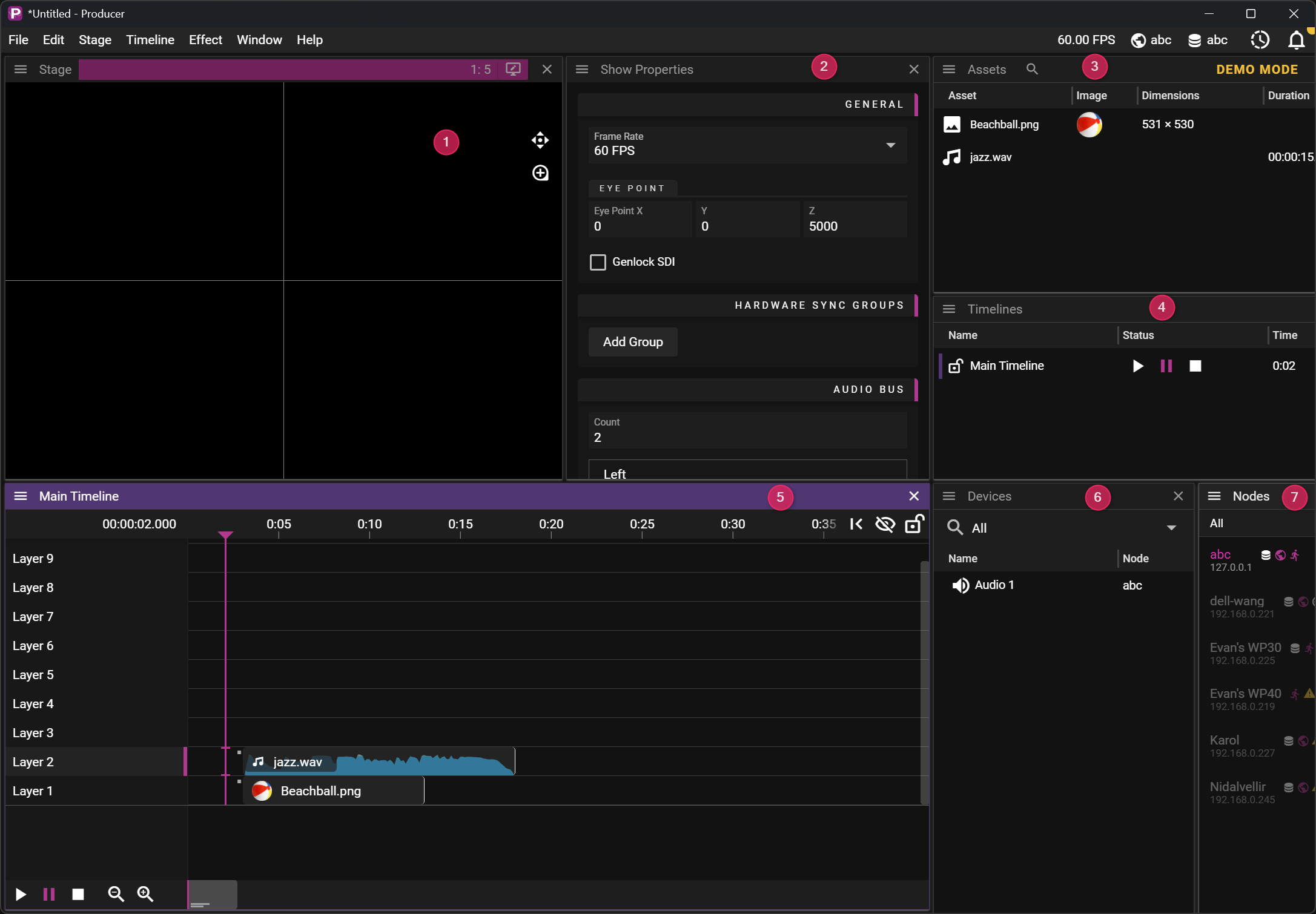
The Producer interface consists of these key components:
- Stage Window - Visual preview showing how media will appear on outputs with positioning tools
- Property Window - Context-sensitive editor that changes based on your selection
- Asset Window - Browse and organize all media files, folders, and preview selected assets
- Timelines Window - Manage all timelines in your show
- Timeline Editor Window - Work with layers, cues, playhead position, and transport controls
- Devices Window - Configure displays, audio devices, and manage network nodes
- Nodes Window - Monitor and control all connected computers in your WATCHOUT system
The Property Window changes its content based on your selection. You will find more details about properties under each window's respective documentation section.Additional Windows
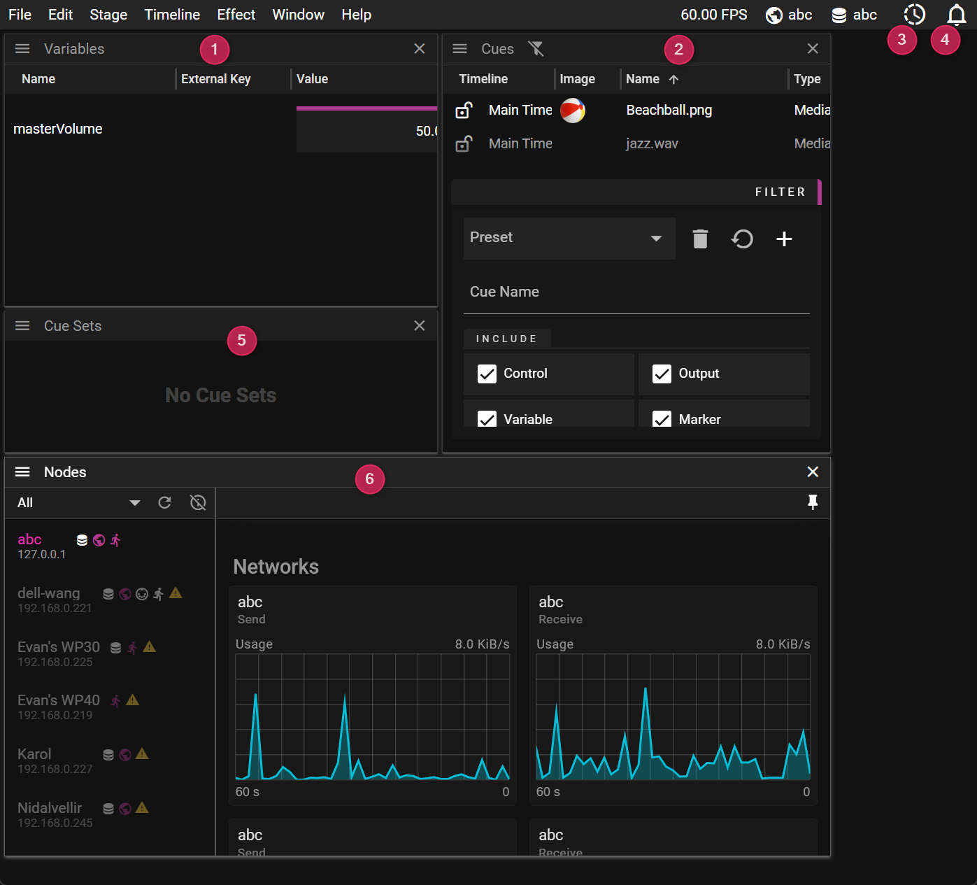 These specialized windows provide advanced functionality:
- Variable Window - Create and manage show variables for dynamic content control and external integration
- Cues Window - View all cues across timelines in a sortable list format
- Activity Monitor - Opens Node Window, also shows ongoing asset transfer job with a yellow dot
- Log Window - View system messages, warnings, and errors for troubleshooting
- Cue Sets Window - Create and manage cue sets for conditional rendering and show variants
- Nodes Window (Expanded) - Detailed view of all nodes with connection status and transfer monitoring
TIP: All windows can be opened from the Window menu. Arrange them according to your workflow needs.
Arranging Windows
WATCHOUT provides a flexible window management system that allows you to customize your workspace:
- Moving windows: Drag any window by its title bar to reposition it
- Resizing windows: Drag the edges or corners of a window to change its size
- Docking assistance: Pink indicators appear when moving windows to show potential docking positions
- Quick maximize:
- Press the Alt key while dragging to expand the window to fill available space
- Double-click a window's title bar to maximize it
- Layout presets: Save and recall your favorite window arrangements using keyboard shortcuts
TIP: You can save up to 9 different window layouts using Ctrl+Alt+[1-9] and recall them with Alt+[1-9].
Keyboard Shortcuts
WATCHOUT includes numerous keyboard shortcuts to speed up your workflow and provide quick access to common functions.
For a comprehensive list of all keyboard shortcuts, see the Keyboard Shortcuts Guide.
Some essential shortcuts include:
- Ctrl+S: Save show
- Ctrl+O: Open a show file
- Ctrl+Z: Undo
- Ctrl+Y: Redo
- Spacebar: Play/pause timeline
WATCHOUT 7 Architecture
WATCHOUT 7 employs a distributed, network-centric architecture with specialized components that work together to deliver synchronized multi-display presentations.
Core System Components
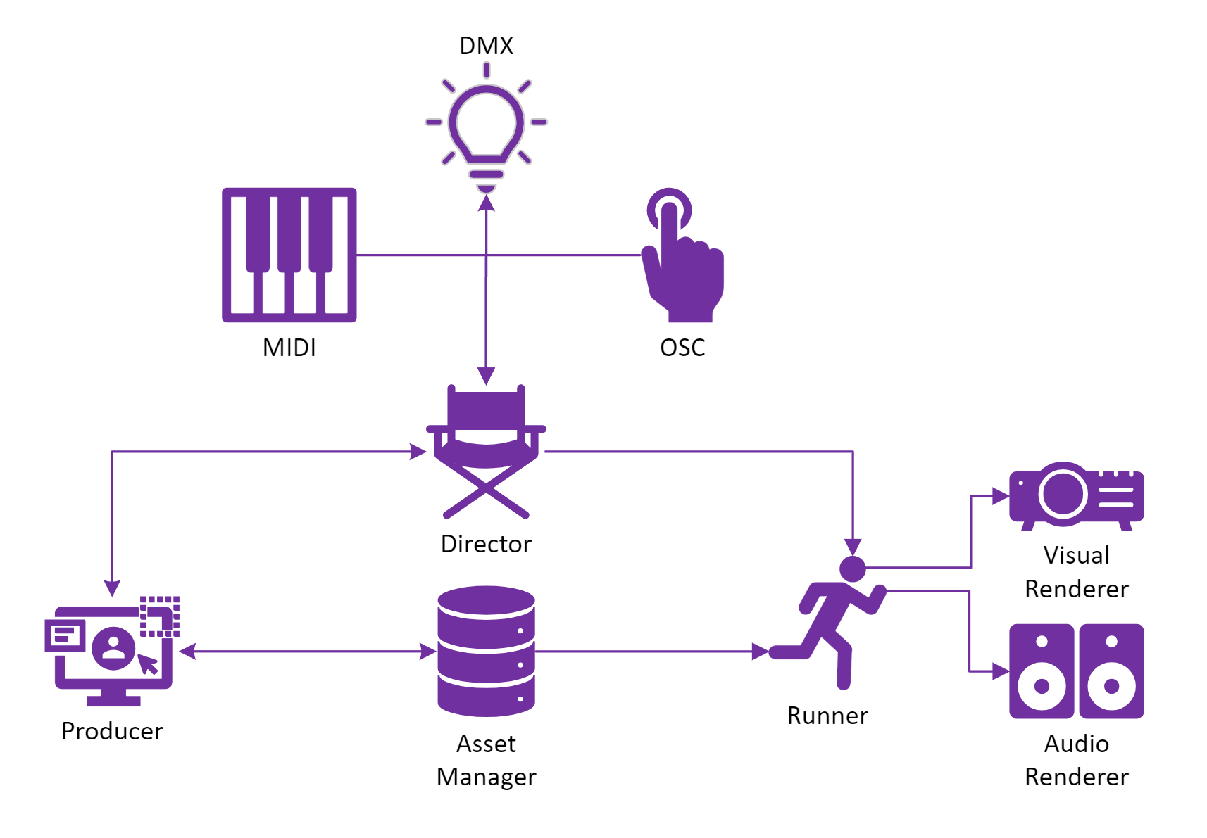
Primary Components
-
Producer
- User interface for show programming and control
- Shows can run without Producer after setup
-
Director
- System coordinator and "brain"
- Distributes show data and manages synchronization
- Acts as NTP time server
- Hosts Operative for external control protocols
-
Runner
- Handles audio and video playback
- Continues functioning even if Director disconnects
- Multiple Runners can be distributed across a network
-
Asset Manager
- Media repository and optimization system
- Distributes assets to Runners as needed
Key Executables
-
Process Manager (
process-manager.exe)- Core component present on all machines
- Handles node discovery and service management
-
Producer (
Producer.exe)- Main user interface for show creation and control
-
Director (
director.exe)- Maintains master show data
- Synchronizes timelines and evaluates expressions
-
Runner (
runner.exe)- Receives show data from Director
- Manages playback logic
-
Renderers
- Visual Renderer (
visualrenderer.exe): Display output - Audio Renderer (
audiorenderer.exe): Sound output
- Visual Renderer (
-
Asset Tools
- Asset Manager (
asset-manager.exe): Media optimization - Asset Watcher (
asset-watcher.exe): Folder monitoring
- Asset Manager (
-
Bridge Services
- LTC Bridge (
ltc-bridge.exe): Timecode input - MIDI Bridge (
midi-bridge.exe): MIDI control - Operative (
operative.exe): Protocol translation (OSC, ArtNet, HTTP)
- LTC Bridge (
Deployment Flexibility
WATCHOUT 7's architecture can scale from compact to expansive configurations:
- All-in-One: Single computer running all services (development/small shows)
- Small Production: Producer/Director on one machine, 1-3 Runners
- Large Production: Dedicated Producer, Director and multiple Runners
- Installation: Headless Director with multiple Runners
System Resilience
- Runners continue playback if Director is lost
- Renderers maintain output if Runner disconnects
- Executables are stopped, started, and restarted automatically
- Distributed processing eliminates single points of failure
Communication Flows
- Discovery: Multicast-based node detection
- Distribution: Show data and asset downloads over HTTP
- Synchronization: NTP-based time alignment
- Control: External protocol translation via Operative, and Bridges
NOTE: Discovery broadcast can be limited to specific network interfaces through Node Window settings. This is useful for redundant setups or when using separate networks for media and control (e.g., Dante audio networks).
This architecture allows WATCHOUT 7 to scale from simple presentations to massive multi-display productions while maintaining frame-accurate synchronization.
Frequently Asked Questions
Show Collaboration
Q: Can multiple users edit a show simultaneously?
A: This is currently not supported, but the intention is to work on this for future releases.
Director Management
Q: I have a show, MyShow, that is currently directed by DirectorA (on node MachineA). In the Devices window I select MachineB, right-click and select "Use as Director". What will happen?
A: The following will happen:
- DirectorA will continue to play MyShow.
- MyShow will be pushed to "Director B" (on "Machine B").
NOTE: If MyShow has any enabled displays when this happens, you will end up with multiple directors trying to push show updates to the same Runner. To avoid this, go to the Devices window, right-click on MachineA and select "Clear Show from Director".
Network Security
Q: Can I run shows using WATCHOUT on a public network?
A: We strongly encourage you to stay on a secure private network when creating and playing shows.
Asset Management
Q: Does WATCHOUT support the use of multiple Asset Manager(s) when creating a show?
A: No, this is currently not supported. Use a single Asset Manager when creating a show.
Settings
WATCHOUT 7 uses two primary types of settings:
- Show-specific settings (stored in the show file)
- System/user settings (stored on the computer)
Show Properties
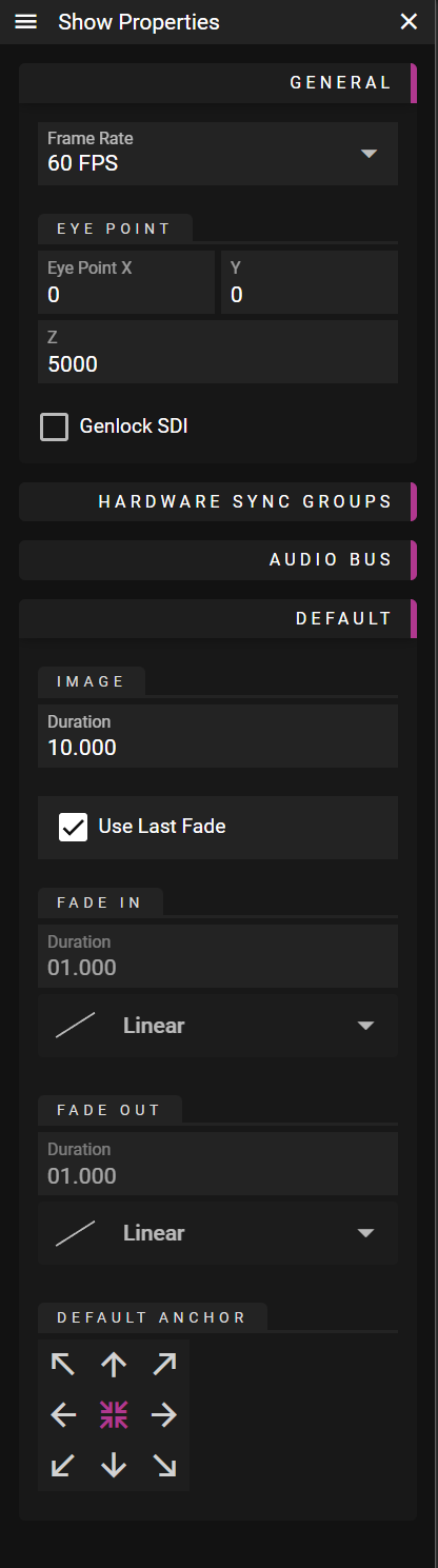
The Show Properties dialog controls fundamental show parameters including:
- Frame rate
- Eye point (for 3D positioning)
You can also configure Show Local defaults, like still image duration.
System Settings
Several important system settings can be found in the Edit Menu.
Tween Colors
Define your custom color scheme for tweens (effects) to improve visual organization in the timeline.
Snap
Toggle snapping on and off. When enabled, cues will snap to grid lines, markers, and other cues.
Legacy Keyboard Mode
This important setting affects how keyboard shortcuts behave:
When ON:
- Spacebar only functions in text fields (not as a play control)
- Play controls (Space, Escape, Numpad-0) affect the last selected timeline
The last selected timeline is indicated by a purple highlight in both the Timeline Editor and Timelines window.
When OFF:
- Spacebar works like most media applications (toggles play/pause)
- Play controls only work when the timeline editor is active (indicated by purple top bar)
Layouts
Window layouts can be saved, loaded, and reset from the Layout submenu of the Window menu.
Saving Layouts:
- Choose Layout from the Window menu
- Select Export...
- Enter a file name and location
- Click Save
Loading Layouts:
- Choose Layout from the Window menu
- Select Import...
- Locate the saved layout file
- Click Open
Keyboard Shortcuts:
- Reset to default: Alt+0
- Save current layout: Ctrl+Alt+[1-9]
- Load saved layout: Alt+[1-9]
Settings File
Computer-local settings store your user defaults, including:
- Which property sections are collapsed/expanded
- Position and size of windows
- Recent files
- User interface preferences
NOTE: Both layout and settings gets included when you Create Archive (from the File Menu)
STAGE & DISPLAYS
In the world of WATCHOUT, Stage is a canvas and displays are windows onto that canvas.
- Each display server has a total pixel output of 8 x DCI 4k (8 x 4096 x 2160 pixels).
- A display server may utilize multiple GPUs to display content on multiple outputs.
By adding a display to Stage, you are effectively associating a physical output from a graphics card. It could for instance be a:
- Displayport output on a WATCHPAX 62S.
- SDI output on a WATCHPAX 62C.
- NDI output from a WATCHPAX 62B.
STAGE
The Stage window in Producer has two main purposes:
- Preview the show.
- Edit the show.
Below we outline some important concepts related to Stage. You may also read more about Stage Properties here.
COORDINATE SYSTEM
Stage uses a right-handed coordinate system with a horizontal X-axis (red), a vertical Y-axis (green), and the Z-axis representing depth (blue). It is possible to visualize the coordinate system by holding your right hand in front of you. Hold your hand so that the thumb points to the right, your index finger points up and the middle finger points towards you. These three fingers then represent the x-, y- and z-axis where the:
- Thumb points along the positive x-axis.
- Index finger points the along positive y-axis.
- Middle finger points the along positive z-axis.
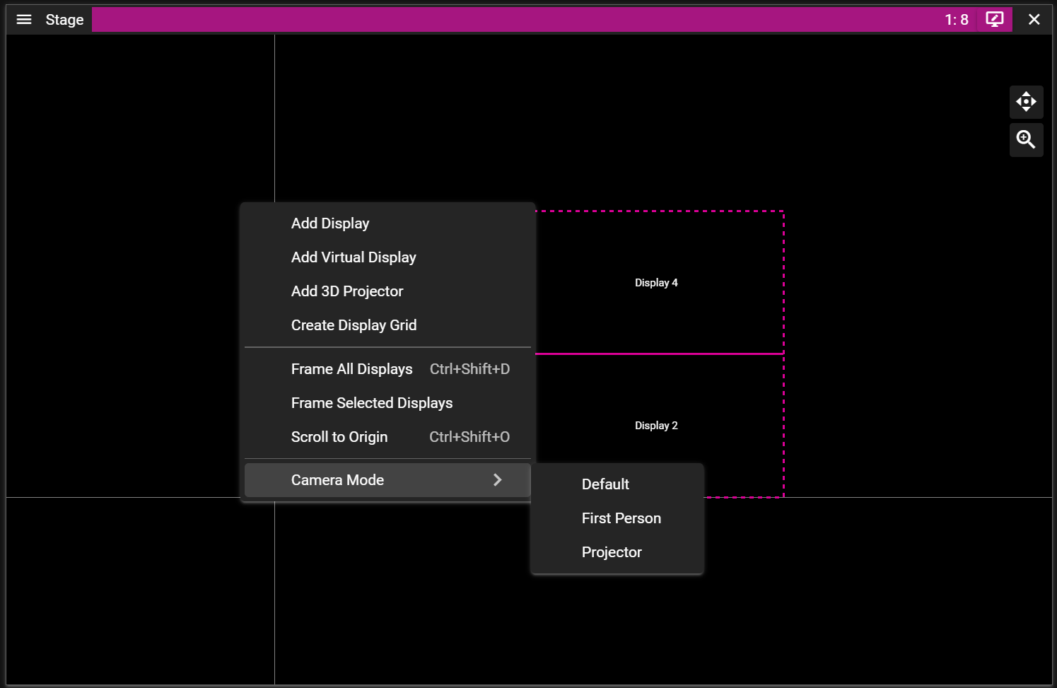
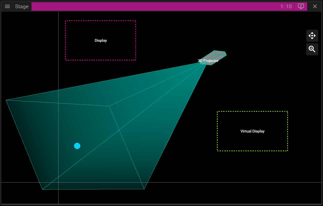
MENU
You can access the Stage menu from the top left corner of the window. It can also be found at the top menu bar of Producer under Stage.
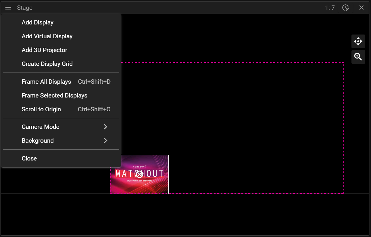
- Add Display creates a new display.
- Add Virtual Display creates a new virtual display.
- Add 3D Projector creates a new projector.
- Create Display Grid opens a dialog allowing you to add multiple displays in a single operation.
- Frame All Displays will change the scale of Stage so that all displays become visible.
- Note that this does only work in Default mode.
- Frame Selected Displays works like Frame All Displays but only by using the displays currently selected.
- Scroll to Origin resets the view to the default location.
- Camera Mode opens a sub menu allowing you to switch between different camera modes.
- Close the Stage window.
EDIT MODES
There are two edit modes in Stage:
- Display Edit Mode.
- Cue Edit Mode.
You can toggle between the edit modes by clicking the top bar in Stage. Notice that the color of the top bar changes depending on which edit mode you are in.
In display edit mode you can select and edit displays and in cue edit mode you can edit cues.
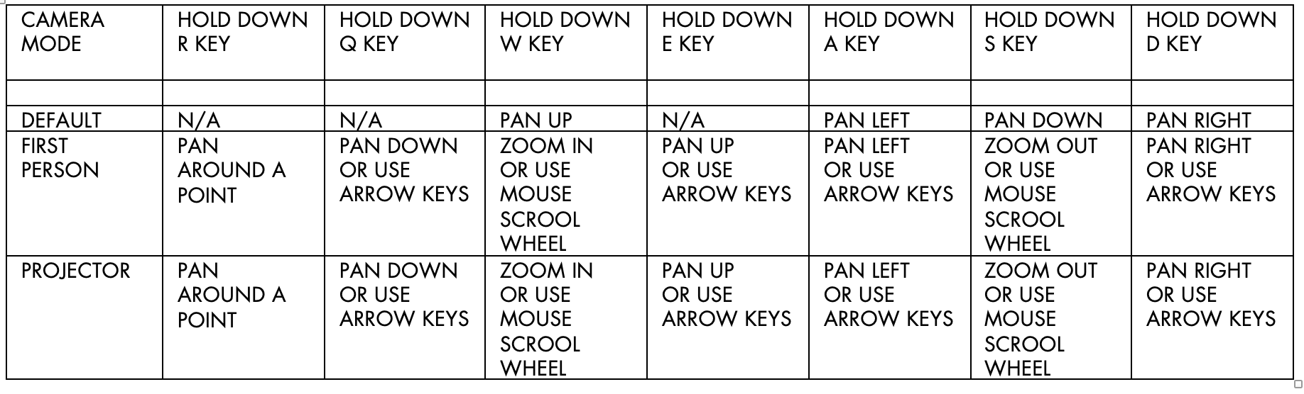
CAMERA MODE
Stage has three camera modes:
- Default.
- First Person.
- Projector.
Right-click in the Stage window to switch between these modes based on your needs.
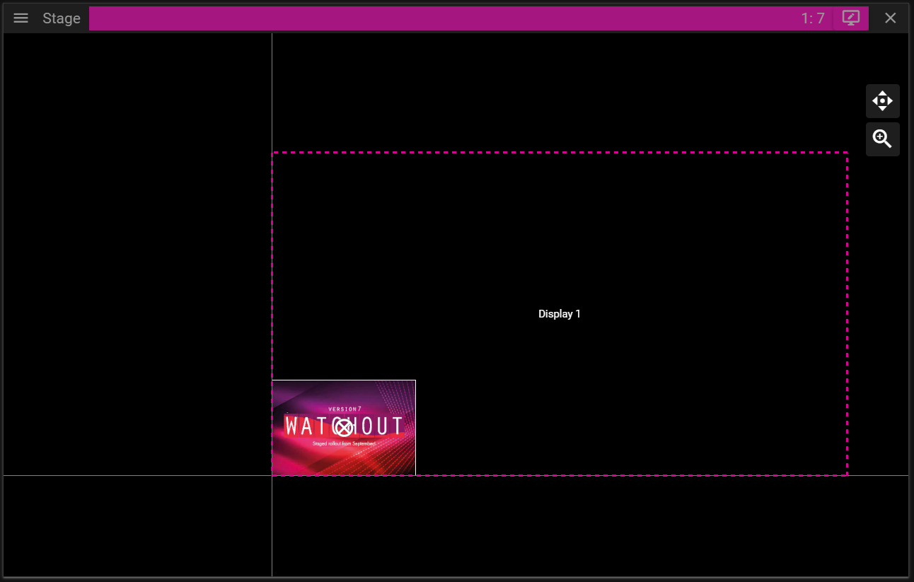
DEFAULT CAMERA MODE
When starting WATCHOUT Producer, the Stage window will be in the Default camera mode. This mode is ideal for creating shows without 3D content, although it still supports 3D editing.
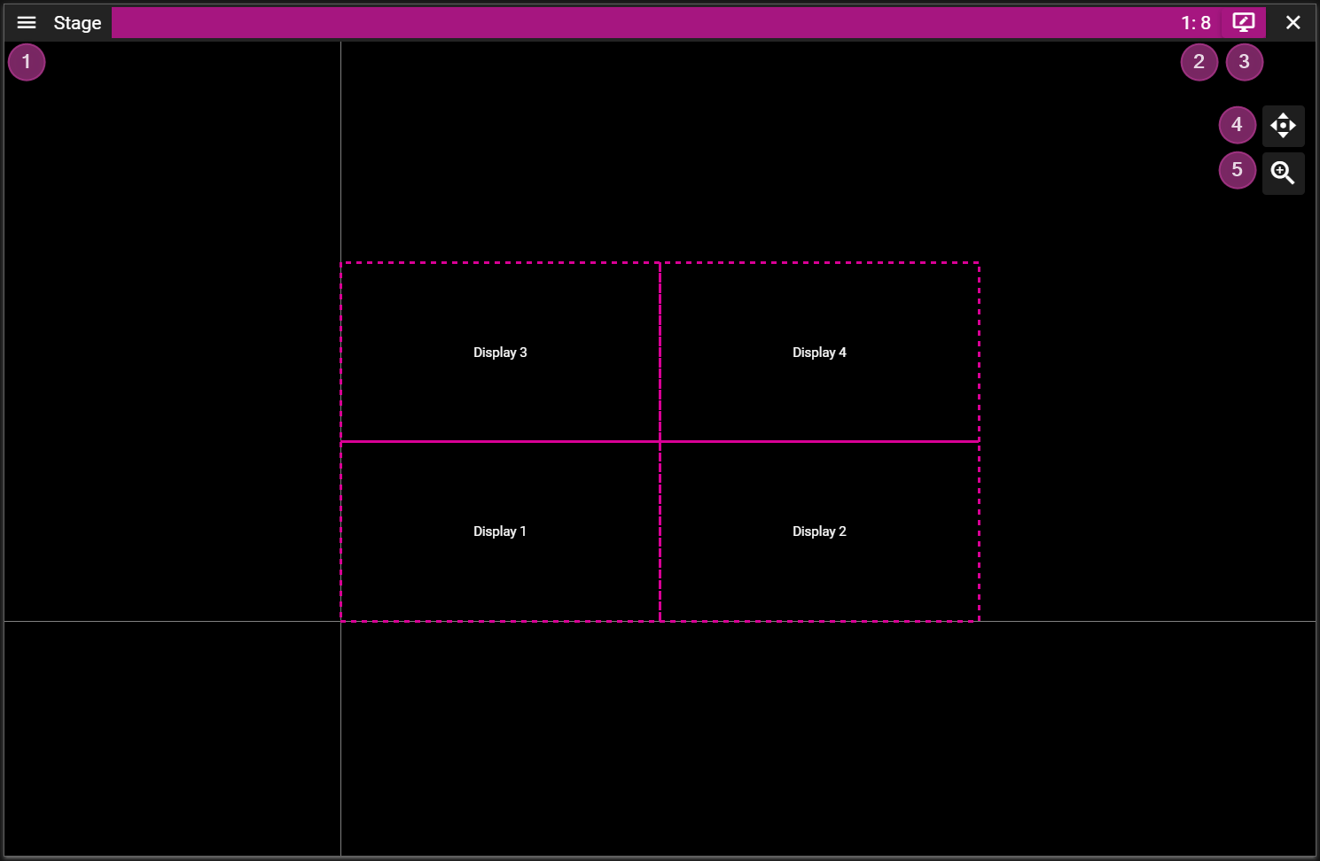
- Stage Menu.
- Stage Scale shows the active Stage scale.
- Use the mouse scroll wheel or the scale button to change the scale.
- Edit Mode can be switched by clicing on the top bar of the Stage window.
- Pan the view by clicking and dragging the pan button.
- Scale the view by clicking and dragging the scale button
- Note that you may also scale using the scroll wheel. This zoom operation will scale towards, or away from, where the mouse points.
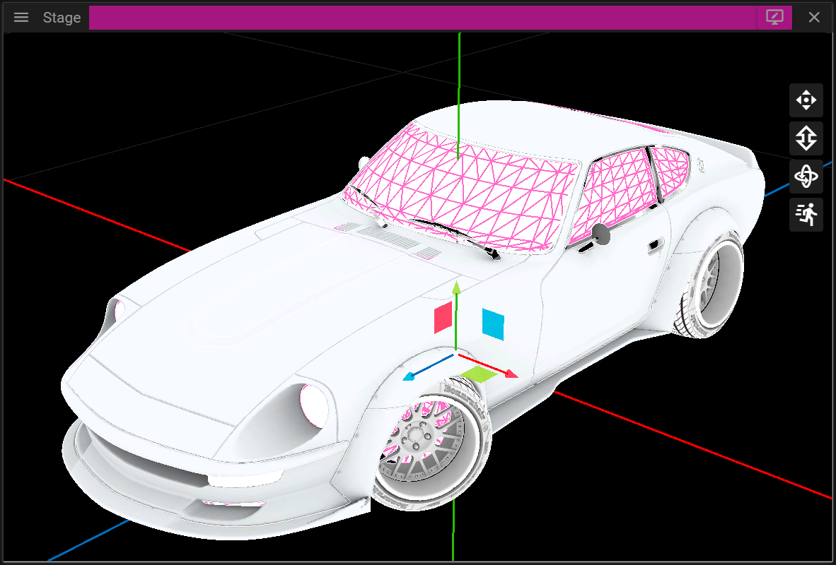
FIRST PERSON CAMERA MODE
Designed for 3D tasks such as 3D mapping, the First Person camera mode offers greater navigation freedom compared to the Default mode.
This view uses a focus point, white sphere, to decide zoom target and what point to orbit around.
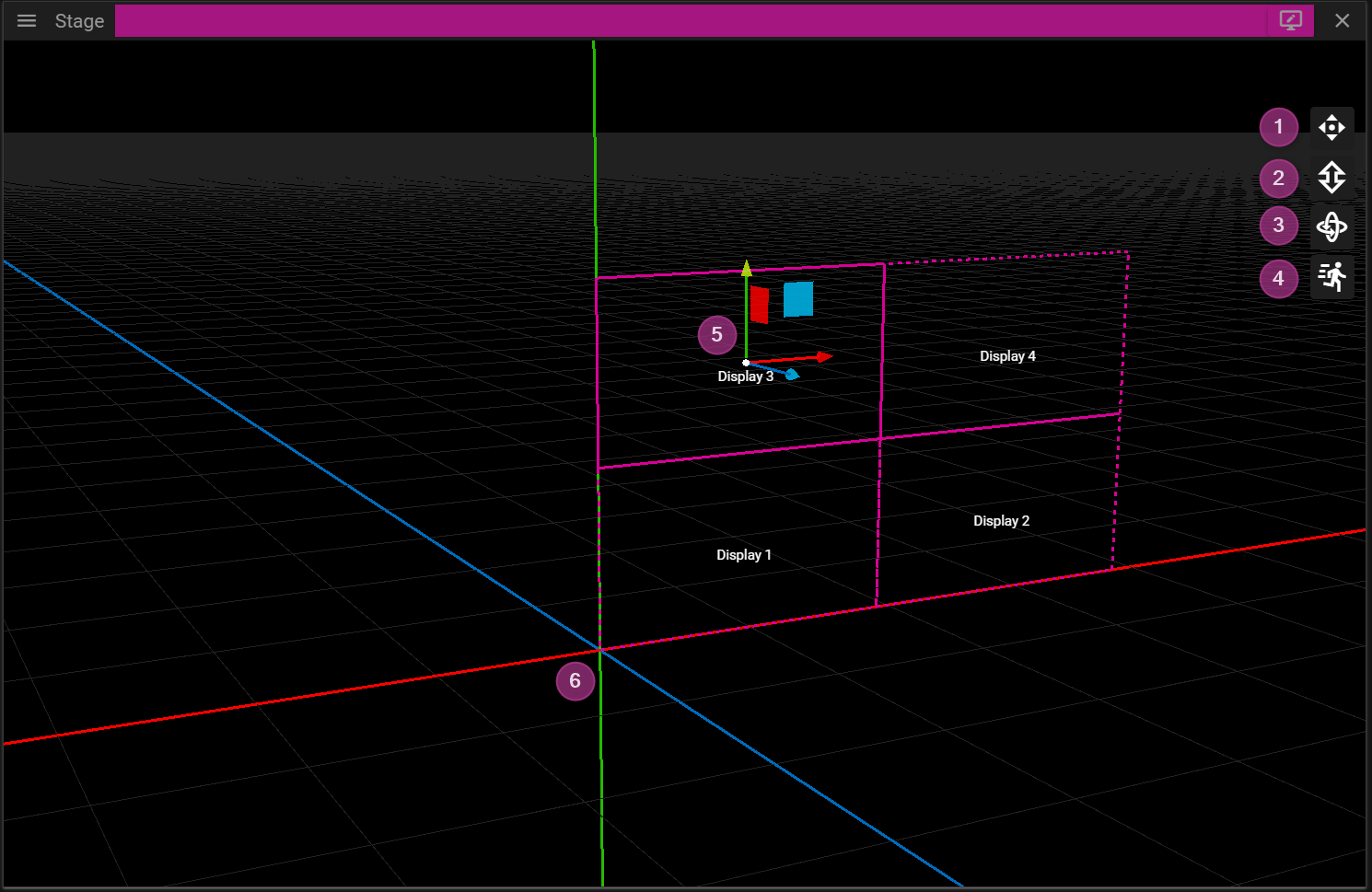
- Pan the view by clicking and dragging the pan button.
- Zoom the view by clicking and dragging the zoom button. The camera will zoom towards the focus point.
- Note that you may also zoom using the scroll wheel. This zoom operation will zoom towards (or away from) where the mouse points.
- Orbit the view around the focus point by clicking and dragging the orbit button.
- Velocity Control is used to adjust the camera movement velocity.
- Lowering the camera velocity is epspecially useful during 3D projector position fine tuning.
- Axis gizmo is used to move cues and displays in 3D. Click and drag drag an axis arrow (or a plane) to move objects.
- Notice that the positive direction of the axes are represented with arrows.
- Coordinate System origin with axes x (red), y (green) and z (blue).
PROJECTOR CAMERA MODE
In Projector camera mode, you view the virtual scene from the projector’s perspective. This is useful for projector positioning and calibration.
You may enter projector mode by either:
- Clicking on the Frame Display button (magnifying glass), in the Display Properties window.
or - By double-clicking a projector.
or - By right clicking in the Stage window.
The navigation in this mode mimics the navigation in the First Person mode with the exception that the scroll wheel zooms to target instead of zooming towards a focus point.
There is more information about the Projector mode in the 3D Mapping chapter.
MOVEMENT & SNAPPING
There are two ways to change the position of a display or cue:
- From the Properties window.
or - Inside the Stage window.
The Properties window will show a section named Position (or Position and Size) once a display or cue has been selected. Note that if you select multiple displays or cues you can edit them in a single operation.
To move a display, or cue, in the Stage window you need to click and drag it. Keep in mind that you may only select and move objects if you are in the correct Edit Mode.
If you hold the shift key you will get help lines that simplify movement along a specific axis.
During movement objects will try to snap to each other. The snapping can be toggled on/off from Edit/Snap found in the top menu bar of Producer.
You may tempoararily disable snapping by holding the Ctrl key while moving an object.
STAGE TIERS
Stage Tiers are layers in the Stage window. They can be used to restrict media cues, on layers or on timelines. For example, if two overlapping displays are located on the same tier, in the Stage window, WATCHOUT will automatically create a soft edge blend between them. If you want to avoid the edge blend when two, or more, screens overlap in the Stage area, you would put them on different tiers.
COMPOSITION MODE
If a Composition's timeline window is active, Stage switches to composition mode. This means that Stage only shows cues that are part of the active composition. To make it clearer that Stage is in composition mode, a frame is added around the Stage window and an icon on the top bar.
KEYBOARD NAVIGATION
STAGE PROPERTIES
In this section you will learn about Stage Properties which is shown if you click the Stage background.
FILTER
In WATCHOUT there is a concept called tiers that allows you to filter what cues are being rendered for a specific display. You may assign one or multiple tiers to displays in the Display Properties and you may do the same for cues in the Cue Properties.
Before WATCHOUT renders the content for a display it will filter out all cues that do not match the tier configuration of the display. This is easiest to explain with an example:
- Display A is assigned two tiers, Base and Tier 1.
- Cue A is assigned Base.
- Cue B is assigned Tier 1 and Tier 2.
- Cue C is assigned Tier 2.
What will be considered as valid content for Display A?
Cue A and Cue B have at least one tier that matches Display A and are thus considered as valid content. Cue C however only has Tier 2 which is not part of the tier configuration for Display A and thus Cue C is not considered as valid content for Display A.
The Filter section in the Stage Properties can be used to create new tiers and preview what happens if a tier is not active by toggling its visibility.
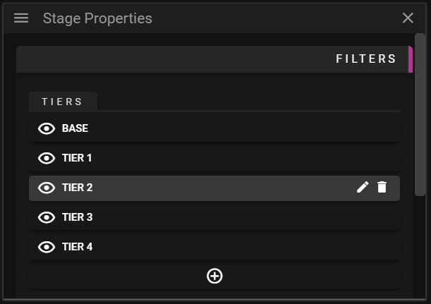
- Tiers shows all tiers present in the show.
- Base is assigned to display and cues on their initial configuration.
- This tier cannot be removed from the show.
- Eye icon can be used to toggle the visibility of cues in Stage based on their tiers configuration.
- It is enough that one of the tiers of a cue is kept visible for the cue to stay visible in Stage.
- Pen icon can be used to edit the name for a tier.
- Note that by changing the name of a tier will update all displays and cues that refer to that tier.
- Thrash can icon can be used to remove a tier.
- Plus icon can be used to create a new tier.
- Base is assigned to display and cues on their initial configuration.
APPEARANCE
This section is used to change the appearance of Stage. You may edit the Stage background by either setting a checker pattern or by defining a custom background color.
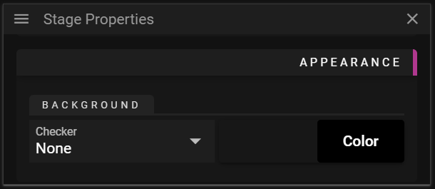
- Checker
- None means that no checker pattern will be rendered in the background.
- Small means that a small checker pattern will be used as the background.
- Medium means that a medium checker pattern will be used as the background.
- Large means that a large checker pattern will be used as the background.
- Color
- Can be used to define a custom background color.
- Note that if a checker background is active this button is disabled.
DISPLAYS
In this chapter you will learn about Stage displays and how these can be configured to control how and where the visual content of a show is rendered.
A Stage display is an object that resides in the Stage window. This object is then associated with a physical display device such as a projector, monitor, LED wall, video wall cube etc to make the show content visible for the audience.
There are three different types of Stage displays in WATCHOUT:
- Display.
- Use this type to represent all flat display devices, as well as projectors when projecting onto a flat screen or a curved screen that can be managed by the Warp feature of WATCHOUT.
- 3D Projector.
- Use this type when projecting onto a complex, 3D object, represented by a 3D model in WATCHOUT. No automatic edge blending is applied, but manual masking can be used to manage overlapping areas.
- Virtual Display.
- Defines a rectangular area in Stage from which you can grab/record the resulting pixels for use as a new media item. This is useful when dealing with displays that have odd resolutions, such as LED wall modules (subsequently managed through an LED wall processor), or to create dynamic textures for mapping onto 3D models.
When a display is selected in the Devices window or in Stage, the Device Properties window becomes active.
You can learn more about adding displays and projectors in the Stage chapter.
DISPLAY PROPERTIES
In this chapter you will learn about the display properties that can be configured.
GENERAL
The General section allows you to edit common data such as Device Name and Device Host.
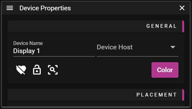
- Device Name can be set to anything you like. This name is shown in the Stage window when you are in Display Edit Mode.
- Device Host is used to set the node on which the display content will be rendered.
- Heart button is used to toggle the activate or deactivate the display.
- Lock button is used to toggle the possibility to edit the display.
- Frame button is used to change the scale in Stage so the selected display(s) are in focus.
- Color button is used to change the frame color of the display. Use it to make it easier to find specific displays.
- The color is also shown in the Devices Window.
In order to see any output from a display on a monitor etc you need to enable it. To enable a display you need to:
- Select the display.
- Make sure you are in Display Edit Mode otherwise you cannot select displays.
- Assign it to a node by setting the Device Host.
- Locate and click the heart icon located in the General section.
PLACEMENT
The Placement section allows you to edit data related to the location of the display in the Stage window.
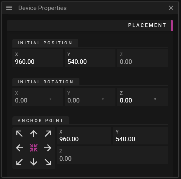
- Initial Position can be changed to edit the position of the display.
- Initial Rotation can be changed to rotate the display counterclockwise around the anchor point.
- Anchor Point defines the origin of the display and it also defines the point around which the display is rotated.
- The anchor widget, with arrows, can be used to move the anchor point to a specific corner, edge or the center of the display.
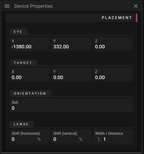
- Projector specific settings:
- Eye defines the point where the projector is located.
- Target defines the target point of the projector when there is no lense shifting.
- Orientation defines the rotation around the direction vector.
- Lense Shift can be used to change where the projector displays its image without changing the position of the projector.
- Width / Distance Ratio can be used to change the shape of the projection frustum.
- Note: During the calibration step when doing 3D Mapping a number of the projector settings above are modified.
In the following example the anchor and rotation of a display is being edited:
PRESENTATION
The Presentation section allows you to edit the tiers of the display.
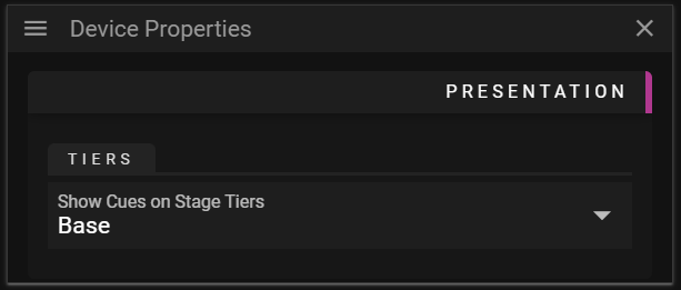
- Tiers
- Show Cues on Stage Tiers can be changed to make the display only render cues that belong to a specific tier.
OUTPUT
The Output section allows you to edit settings related to rendering the referred cues to a display device.
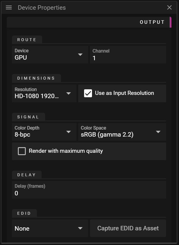
- Route
- Device defines the target buffer for the display. It can be set to GPU, SDI, NDI® and Virtual.
- Channel defines the display device to render the display content to.
- Dimensions
- Resolution is used to define the wanted output resolution. That is the resolution of the buffer to which WATCHOUT renders the cues.
- Use as Input Resolution can be toggled off to use a custom resolution for the display in Stage.
- Signal
- Color Depth defines the number bits used per color channel/component.
- Color Space defines the color space to use for rendering.
- Delay
- Delay frames allows you to delay the rendering of a display. This can be useful to make different displays play exactly in sync.
- EDID
- The drop-down will show all EDID assets available in the Asset Manager currently in use.
- EDID files can be added to the Asset Manager just like any other asset.
- Capture EDID as Asset button captures the current EDID information as an asset and uploads it to the Asset Manager.
- This is only supported on NVIDIA Quadro-based GPUs.
- The drop-down will show all EDID assets available in the Asset Manager currently in use.
WARP
Warping can be useful to make the display output follow an irregular surface, like a curved wall.
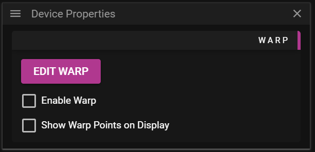
- Enabled toggles warping on or off.
- Show Warp Points on Display toggles the rendering of warp points on or off.
- Edit button opens a window allowing you to modify the warp mesh onto which cues are rendered.
NOTE: You can use a XBox type of controller to adjust the warp points.
For more information look in Appendices / XBox ControllerBelow we edit the warp mesh to change how the output is rendered:
Before:
After:
MASK
Masking can be useful in situations where you want to block parts of the display output. For instance, if you have a pillar between a projector and the projection surface you might want to avoid displaying content on the pillar. This can be achieved by using mask(s).
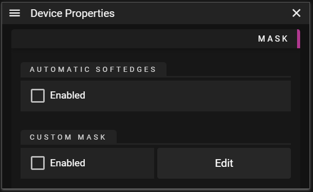
- Automatic Soft Edges allows you to get automatic blending in the areas where displays overlap.
- Enable toggles automatic soft edges on or off.
- Only displays that have this feature enabled will contribute to the soft edge solution.
- It does not matter if the actual display is enabled or not.
- Enable toggles automatic soft edges on or off.
- Custom Mask can be used to block render display outputs for certain pixels.
- Enable toggles custom masking on or off.
- Edit button opens a window allowing you to create and modify mask surfaces.
- The mask layers are local to this display.
DISPLAY MASK EDITOR
The display mask editor allows you to add and edit multiple mask surfaces to your display to limit the areas where the display renders pixels. The Display Mask Editor window shows what the display is currently rendering in Stage. This is to simplify positioning the masks you want to use for your display.
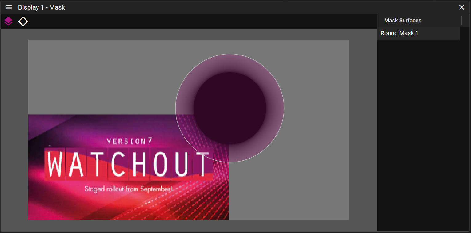
WATCHOUT provides a number of predefined mask surfaces that can be added from the Display Mask Editor menu or by right-clicking anywhere in the Display Mask Editor window.
Once a mask has been added it will be shown in the right column of the Display Mask Editor named Mask Surfaces. It is possible to select multiple masks and edit them together. To do so you may either select them by clicking on their name in the Mask Surfaces column, or you may click or drag select them directly in the mask window.
There are two edit modes for masks:
- Edit Surfaces which allows you to edit one or multiple mask surfaces.
- You can activate this mode by clicking the surface icon found in the upper left corner of the Display Mask Editor.
- You may move, stretch or rotate one or multiple mask surfaces by interacting with the control points that are shown once one surfaces have been selected.
- Select one or more mask surfaces by clicking on them in the Display Mask Editor window. Note that you can hold control or shift button to modify the select operation. You can also select one or multiple masks with a drag select operation or click on the mask surface you want to edit in the Mask Surface section found on the right of the Display Mask Editor window.
- You may also change the name of the mask surface to better convey the type of masking it is used for.
- Edit Points which allows you to edit one or multiple mask surface points.
- You can activate this mode by either clicking the unfilled surface icon found in the upper left corner of the Display Mask Editor or by double-clicking on a mask surface.
- You may edit one or multiple points by selecting them.
- Select one or more points by clicking on them in the Display Mask Editor window. Note that you can hold control or shift to modify the select operation.
- You can read more about the possible edit operations for points in the Mask Point Properties section.
- Add Mask Surface allows you to add a mask surface from a list of predefined surfaces.
Here is a quick demonstration of how to setup masks for your display:
MASK POINT PROPERTIES
The Mask Point Properties can be used to fine-tune a mask. You can activate it by selecting one or more points when you are in the edit point mode of the Display Mask Editor.
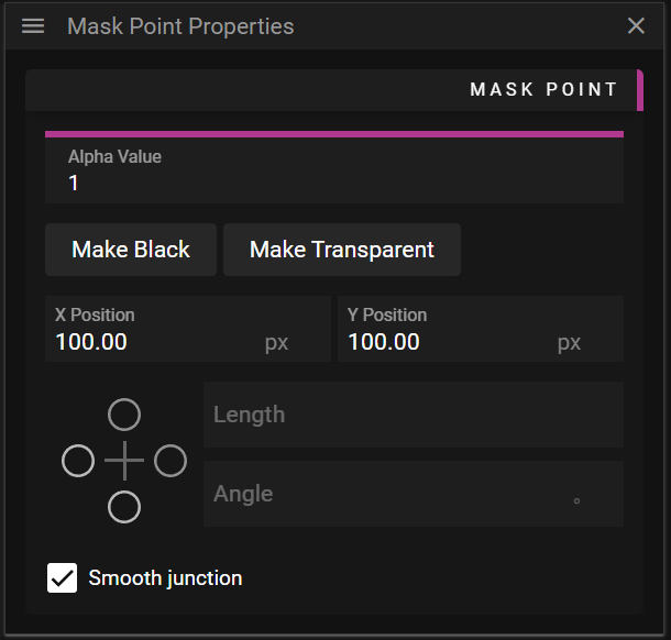
- Alpha Value allows you to define the alpha value for a specific point.
- If alpha is set to 1 it is completely opaque; if alpha is set to 0 is completely transparent.
- Make Black button is a shortcut for setting the alpha value to 1, making the point completely opaque.
- Make Transparent button is a shortcut for setting the alpha value to 0, making the point completely transparent.
- X Position defines the position along the x-axis in pixels, relative to the lower left corner of the display.
- Y Position defines the position along the y-axis in pixels, relative to the lower left corner of the display.
- Control Point Handle widget can be used to select and edit control point handles.
- Length defines the distance in pixels from the control point to the control point handle.
- Angle defines the counterclockwise angle between the control point and the control point handle.
- For instance, if the angle is 0 the point will be located along the local x-axis for the control point.
- Smooth Junction can be toggled on or off to link or unlink the bezier control point handles.
- If it is activated it means that the control point handle on the opposite side (of the handle being edited) will also be affected by edit the operation, in order to maintain a smooth curve.
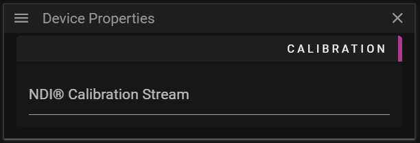
CALIBRATION
Set a NDI® Calibration Stream for the auto calibration system to take over the display. The name of the NDI® stream is given by the auto calibration software.
Assume we want to calibrate two projectors so they produce a continuous image. An auto calibration software then produces a test pattern that is outputted by the two projectors and analyzed by a camera. The auto calibration then makes the necessary changes to align the two projectors so they form a continuous image.
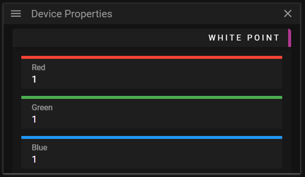
WHITE POINT
The white point allows you to define what color in the output should be considered as white.
TEST PATTERN
This property group contains the possibility to change the output of the display to a specific pattern. This can for instance be useful when working with multiple overlapping display devices.
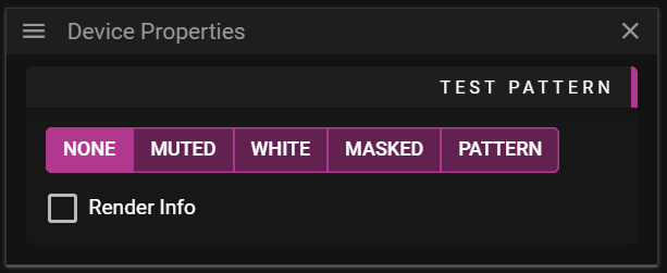
The available patterns are:
- None, outputs the cues associated with the display.
- Muted, outputs nothing for the display even if it is active.
- White, outputs white color.
- Masked, outputs the masks if any.
- Pattern, outputs a checker pattern.
You can also toggle Render Info on and off. This information can be helpful to identify screens if there are many outputs.
VIRTUAL DISPLAYS
Just like an ordinary Stage display a virtual display is defined by a rectangular area in which cues can be placed. However, instead of outputting the rendered cues directly to a physical display device, like a monitor, the virtual display renders the cues to a buffer. This buffer can then be used just like a media asset that can be rendered to an ordinary display or projector.
You can think of this process as the virtual display is recording content and creating a media asset on the fly. The media asset can then be used as a regular cue or as a texture for a 3D model.
The short clip below shows the following sequence:
- Create a virtual display.
- Drag the virtual display from the Devices window to the timeline. This creates a cue using what the virtual display is capturing as a media.
- Change the position of the virtual display, showcasing that it changes how it records the regular media cue.
- Add a 3D model and apply the virtual display to it which means the recorded content will be used as texture.
- Change the position of the virtual display, again showcasing how the virtual display output content changes.
ASSETS & ASSET MANAGER
The Asset Manager in WATCHOUT 7 is an asset management system that stores and organizes your show content. Media files remain separate from show files, which offers several practical benefits:
- Media can be shared across multiple shows
- Files are processed for optimal playback
- Content can be organized in folders
- Assets can be distributed to connected devices
The Asset Manager is network-accessible, allowing team members to connect from different computers simultaneously. It includes a web interface for remote management and supports multiple show files accessing the same assets.
The Asset Manager window lets you browse, preview, and organize assets for your productions.
ASSET MANAGER
You can think of an asset as a piece of data stored in a file, like image or audio data. The assets used to build a show in WATCHOUT are handled by the Asset Manager. The purpose of the Asset Manager is to:
- Prepare assets for being used in WATCHOUT shows.
- Organize assets.
- Share assets between projects and users.
The Asset Manager does not need to be located on the machine running Producer, it can be on any node available on your network. Since preparing assets can be a time-consuming and CPU and GPU intensive task, it can be beneficial to share a powerful machine among creators.
NOTE: You may organize your assets into folders just like any other file system.
To make use of assets they need to be added to the show. This is done by either dropping them to a Timeline or to the Stage window which creates a cue. This can be used to configure how the data stored in the asset is visualized/played.
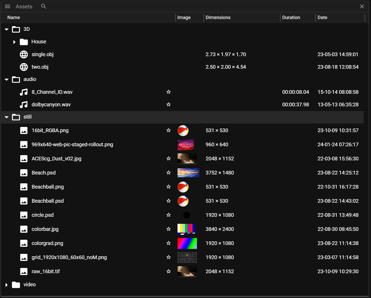
- Magnifying glass icon is used to open the search interface.
- Name will show the name of the asset. This can be edited in the Asset Properties.
- Image will show a thumbnail of the asset.
- Dimensions shows the resolution for media and the size for 3D models.
- Duration shows the time duration of the asset (available for videos and audio).
- Date shows when the original file was created (this does not show when the asset was added to Producer).
NOTE: Not all assets have a thumbnail, dimension or duration.
CUSTOMIZING COLUMNS
Right-click any column header to show or hide columns. Click a column header to sort by that property; click again to reverse the sort order. These column settings apply throughout Producer's table views.
MISSING ASSETS
Assets that are missing or failed to optimize are shown with a warning indicator. This helps you quickly identify problems before showtime. Missing assets typically occur when the original source file has been moved, renamed, or deleted.
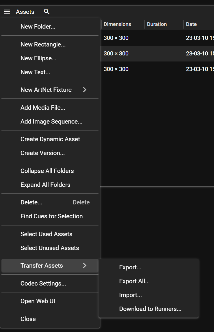
ASSET MANAGER MENU
New/Add
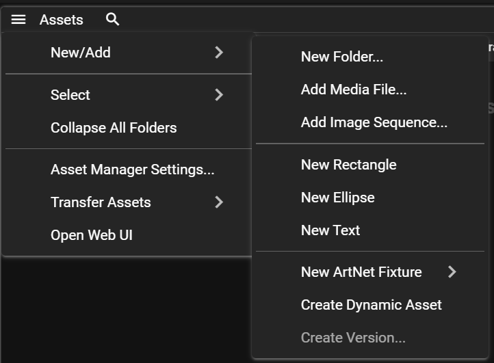
- New Folder - Create a folder to organize assets.
- Add Media File - Add an asset from your disk.
- Add Image Sequence - Add an image sequence folder from your disk.
- New Rectangle / Ellipse / Text - Create a shape asset.
- New Art-Net Fixture - Create an Art-Net fixture asset.
- Create Dynamic Asset - Create a new dynamic asset, or convert the selected asset to one.
- Create Version - Clone the selected asset with a new name.
Select
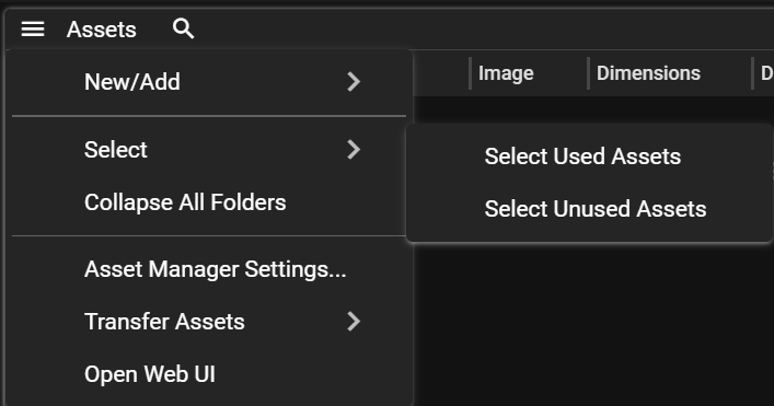
- Select Used Assets - Select all assets used in the show.
- Select Unused Assets - Select all assets not used in the show.
Other
- Delete - Delete selected assets.
- Select Cues Using Asset - Find all cues that use the selected asset. See Select Cues Using Asset.
- Collapse All Folders - Close all open folders.
- Asset Manager Settings - Configure codec mappings and bandwidth limits.
- Transfer Assets - Export, import, or download assets. See Transfer Assets.
- Open Web UI - Open the Asset Manager web interface in a browser.
ADDING ASSETS
To add an asset to the Asset Manager you can either:
- Go to the menu and select New Media File (or New Image Sequence).
OR - Drag and drop a file from your file system to the Asset Manager.
Once the asset has been added, the Asset Manager will begin to prepare the asset for use in WATCHOUT shows. The asset goes through four steps:
- Uploading (only necessary if you are using a remote Asset Manager).
- Pending which means it is waiting to be optimized for WATCHOUT usage.
- Optimizing which means it is being optimized for WATCHOUT usage.
- New which means it is ready to be used in WATCHOUT shows.
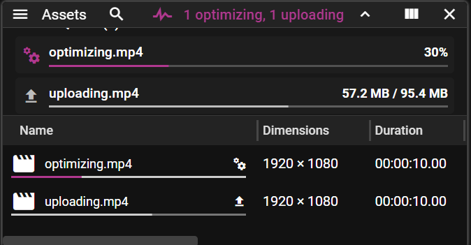
PROGRESS INDICATORS
The following images show
uploading.mp4(grey progress bar, upload icon) andoptimizing.mp4(colored progress bar, cog icon) being processed simultaneously.- When the window is not focused, a pulsing icon in the center indicates background activity.
- When the Asset Manager window is focused, an activity indicator appears in the top right corner.
- Click the chevron to expand the job queue and view progress details for each asset.
SELECTING ASSETS
You select an asset by clicking on it. Producer also supports holding the Control/Shift-key to alter the select operation. You can also use Control+A to select all assets in the Asset Manager.
When an asset is selected, the Properties window is populated with asset information - Asset Properties.
REMOVING ASSETS
Select an asset(s) in the list and click the Delete key or select Delete in the Asset Manager menu.
FOLDERS
Producer supports importing complete folder structures which is very useful if you have already organized your assets in a specific way. To add a folder structure to the Asset Manager simply drag and drop it in the Asset Manager window.
You can also create or delete new folders from the Asset Manager menu. To move an asset to a specific folder you select and drag it to the folder of your choice.
SEARCH
Click on the magnifying glass icon at the top of the Asset Manager to open the asset search interface.
Enter text in the search field to start your search. You can further narrow down the search result by:
- Selecting a specific asset type in the drop-down menu.
- Showing newly created assets (assets marked with a star).
- Showing assets based on which cues are currently selected on your Timeline(s).
- Showing assets that are currently being prepared. Please see adding assets.
Hide the search functionality by clicking on the cross on the far right.
SELECT CUES USING ASSET
Sometimes it might be helpful to find cues that are using a specific asset. To do this you need to:
- Select the asset(s) of interest.
- Right-click in the Asset Manager window and select Select Cues Using Asset.
- The matching cues are selected in the Cues window.
TIP: Asset replacment, replace an asset across your entire show in seconds:
- Select the asset to replace in the Asset Manager.
- Right-click and select Select Cues Using Asset.
- All matching cues are now selected in the Cues window.
If you have many cues, the Cues Window filter "Selected Cues Only" may come in handy - Drag the new asset onto any selected cue—all update at once.
No need to manually find and update each cue individually.
Asset Types
WATCHOUT supports the following asset types:
- Image
- Video
- Audio
- 3D Model
- Display settings
- Composition
- Dynamic
- Shape
- Font
- Art-Net Fixture
- GDTF Fixture
- Art-Net Recording
- Folder
In the section below there is more information about each asset type. Some of the asset types support a wide variety of formats and codecs. If you are looking for more information about formats and codecs you can find that here.
IMAGE ASSET
Image assets are used to fill WATCHOUT shows with pixels.
WATCHOUT supports the most common image formats including JPG, PNG, WebP, and TIFF. For a complete list of supported formats and optimization recommendations, see the Image Formats section.
To display an image asset in a show, and control how its pixels change over time, it must be dropped to the timeline (or Stage) to create a new cue. The asset can also be added to the show by dropping it on an already existing cue.
VIDEO ASSET
Video assets are used to fill WATCHOUT shows with pixels that change over time. A video asset consists of a sequence of frames where each frame represents a point in time and what pixels should be displayed at that specific point.
WATCHOUT supports the most common video formats including MP4, MOV, and MPEG-2. For a complete list of supported formats and optimization recommendations, see the Video Formats section.
If any of the formats above are added to the Asset Manager a video asset will be created. Note that some formats may generate a composition asset, you can read more about that here. Also note that WATCHOUT also supports image sequences. Image sequences can be added from the Asset Manager menu and the resulting asset becomes a video asset.
To display a video asset in a WATCHOUT show, and control how its pixels change over time, it must be dropped to the timeline (or Stage) to create a new cue. The asset can also be added to the show by dropping it on an already existing cue.
AUDIO ASSET
Audio assets are used to fill WATCHOUT shows with sound.
WATCHOUT supports the most common audio formats including WAV, MP3, FLAC, and AAC. For a complete list of supported formats and optimization recommendations, see the Audio Formats section.
If any of the formats above are added to the Asset Manager an audio asset will be created.
To play sound from an audio asset in a WATCHOUT show it must be dropped to the timeline (or Stage) to create a new cue. The asset can also be added to the show by dropping it on an already existing cue.
3D MODEL ASSET
3D model assets can be used to add 3D mapping to WATCHOUT shows. This allows you to project media onto real-world, non-flat, physical objects such as 3D-printed miniatures or even full size objects, like cars. Note that 3D mapping is not the only reason to use 3D models. You may also use 3D models to display media content on non-flat surfaces, like a sphere, in the virtual world and then display the output on a regular screen.
WATCHOUT supports the following 3D model formats:
- .obj
- .gltf
- .glb
- .3ds
If any of the formats above are added to the Asset Manager a 3D model asset will be created.
To make use of a 3D model in a WATCHOUT show it must be dropped to the timeline (or Stage) to create a new cue. The asset can also be added to the show by dropping it on an already existing cue.
DISPLAY SETTINGS ASSET
Display setting assets are used to bring preconfigured displays into WATCHOUT shows. For instance, the display configuration may come from a software that automatically re-calibrates projectors each morning at a WATHOUT show site.
WATCHOUT supports the following display settings formats:
- .mpcdi
If any of the formats above are added to the Asset Manager a display settings asset will be created.
To make use of a display settings asset in a WATCHOUT show it must be dropped to Stage. This will generate displays with the configuration provided by the display settings asset.
COMPOSITION ASSET
Composition assets contain multiple assets of different types. For instance a composition asset may contain both a video and an audio asset.
If a file containing both video and audio data is added to the Asset Manager a composition asset will be created. The composition will be displayed as three assets in the Asset Manager. One asset to represent the composition, one to represent the video data and one to represent the audio data. You can click the arrow next to the composition asset in the Asset Manager to show (or hide) a list of the assets it contains.
To make use of a composition asset in a WATCHOUT show it must be dropped to the timeline (or Stage) to create a new cue. The asset can also be added to the show by dropping it on an already existing cue. If a composition asset is added to the timeline (or Stage) a composition cue will be created. Note that you may choose to only drop the video or audio asset to the timeline (or Stage), then no composition cue will be created, just a regular cue referring to the specific video or audio asset.
DYNAMIC ASSET
Dynamic assets are containers for other assets. The contained assets are also referred to as dynamic asset versions or just versions. The version which was last added to the dynamic asset becomes the active one, and it is this asset version that will be used by cues referring to the dynamic asset. The dynamic asset can only carry two versions, the active version one and the previous version.
The dynamic asset manages the lifecycle of the versions it contains. This means that if a new asset is added to the dynamic asset it becomes the active version, the version which was active becomes the previous version and the version which was the previous version is removed. This is convenient for a few different scenarios. For instance, it is handy if you have an image you want to finetune, in let say Photoshop, and you want to have changes to the image directly reflect in the show. Another scenario where this is useful is if you have an asset that is automatically updated based on some external input. For instance you could have an asset that reacts to how the weather in the real world changes over time.
To create a new dynamic asset you can use the Asset Manager menu or the right click context menu and navigate to New Dynamic. This will create an empty dynamic asset. By dropping asset files from your disk to the dynamic asset you can add versions to it. You may also add versions to the dynamic asset by using the Asset Watcher.
You can click the arrow next to the composition asset in the Asset Manager to show (or hide) a list of the assets it contains. The asset displayed at the top of the list is the active asset version (this is also shown in the Asset Properties when the dynamic asset is selected). Note that assets contained by a dynamic asset cannot be directly added to the show. The reason behind this is that these assets can be automatically removed by the Asset Manager if a new version is added, which would result in a cue referring to a removed asset.
To make use of a dynamic asset in a WATCHOUT show it must be dropped to the timeline (or Stage) to create a new cue. The asset can also be added to the show by dropping it on an already existing cue.
SHAPE ASSET
Shape assets are used to add rectangles, ellipses and texts to WATCHOUT shows. By default the Shape asset is wrapped inside a dynamic asset. This allows you to edit it multiple times and have old version of it to be automatically removed.
To create a new dynamic asset you can use the Asset Manager menu or the right click context menu and navigate to New Shape. This will create a default shape asset.
A shape asset is represented using scalable vector graphics (svg), but you are still required to define the resolution to which it should be rasterized. Put in other words, there is no dynamic rasterization happening when the shape is rendered. It is your responsibility to find a suitable resolution that fits your needs.
Note that text shapes require a font asset to be available on the Asset Manager.
You can find more information about shape assets and how they can be edited in the asset properties for shapes.
FONT ASSET
Font assets are needed to be able to display text shapes. To add a font to your Asset Manager you need to drop the font to the Asset Manager window.
ART-NET FIXTURE ASSET
Art-Net fixture assets are used to control Art-Net related aspects of you WATCHOUT show.
To create a new Art-Net fixture asset you can use the Asset Manager menu or the right click context menu and navigate to New Art-Net Fixture and select one of the following:
- 1 ch Generic
- 10 ch Generic
GDTF FIXTURE ASSET
A General Device Type Format (GDTF) asset is a special case of an Art-Net fixture asset with a predefined map of a fixture properties linked to Art-Net channels. GDTF is an open-source format with a unified definition for the exchange of data for operating intelligent luminairs.
For more information about the GDTF format visit: https://gdtf-share.com/
ART-NET RECORDING ASSET
A Art-Net recording assets is a file stored in a ndjson format created by the Art-Net Recording app that is supplied with the WATCHOUT installation. The Art-Net recording asset can contain up to 512 Art-Net channels and their recoded values over time.
For more information about Art-Net recording look at Art-Net Recording
FOLDER
Folder assets, or just folders, provide a way to organize your assets into folders.
To create a new folders you can use the Asset Manager menu or the right click context menu and navigate to New Folder.
ASSET PROPERTIES
The Asset Properties window provides information about the selected asset(s) along with a few possibilities to edit the asset(s).
ASSET
In this section you can find information about the asset(s) that are currently selected.
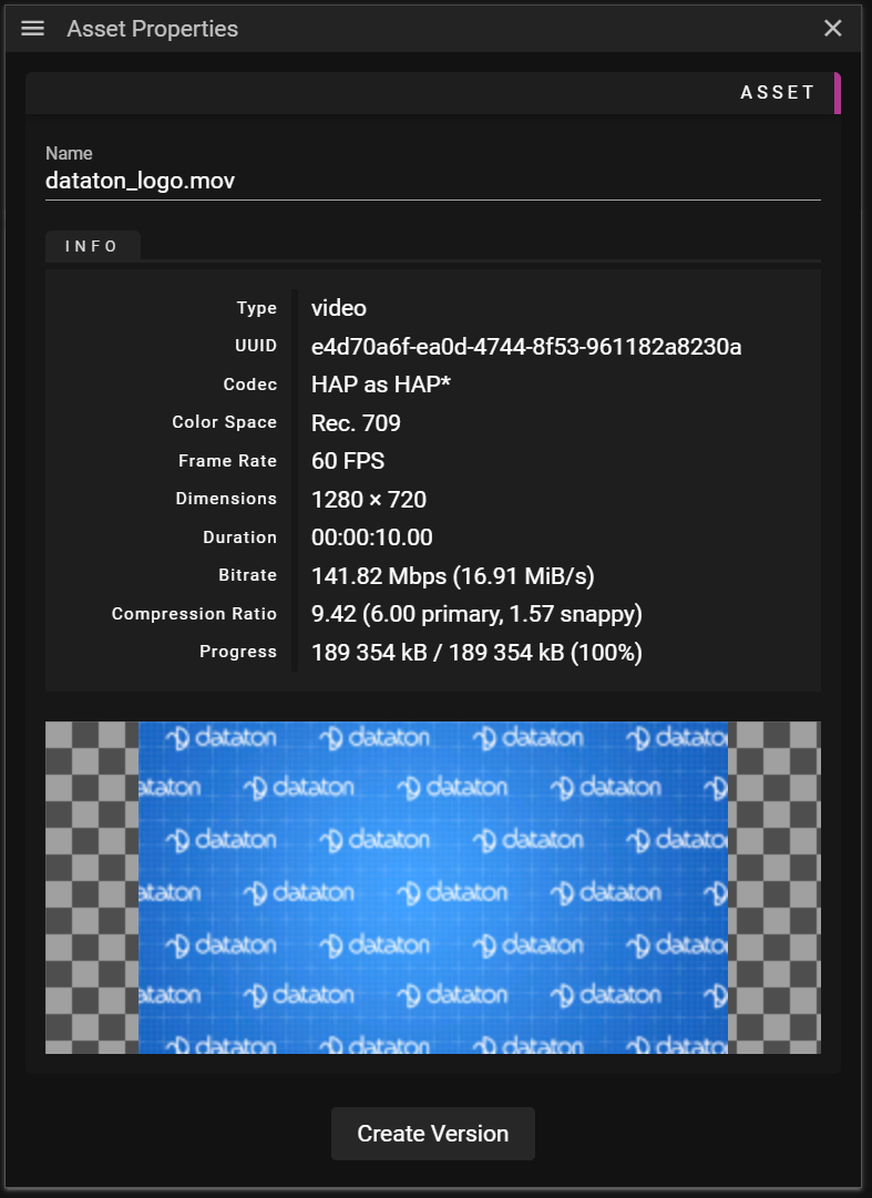
The Name field shows the name of the asset, which is this name that is displayed in the Asset Manager. You may edit this name to if you prefer, otherwise the asset uses the original file name of the asset.
The information displayed in the Asset Properties depends on what type of asset(s) is currently selected.
- All asset types:
- Type contains information about the asset type.
- UUID is a universal unique identifier for the asset. When a new asset is added, or a new version of an asset is added, a new UUID is created.
- Note that you will get two different UUID even if you add the same asset twice to the Asset Manager.
- Video/Image/Audio
- Progress is updated while an asset is being prepared for WATCHOUT.
- It will display "processed size"/"estimated final size" "(progress in percentage)".
- Note that once the asset preparation is done the "estimated final size" will show the actual size on the storage device.
- Video:
- Frame Rate shows the number of frames played per second.
- Bit Rate shows the average number of bits that will be streamed per second to play the video.
- Video/Image:
- Codec contains information on the format used to store the data.
- Note that it shows information in the form: "Original playback format" as "WATCHOUT playback format".
- Color Space shows the color space used during playback.
- Dimensions shows the resolution of the asset.
- Compression Ratio shows how compressed the transcoded video is compared to its uncompressed form.
- A compression ratio of 10 means that the video is 10 times smaller than its uncompressed form.
- The type of compression along with their contribution to the total compression is also shown.
- Multiply the values to get the total compression.
- Codec contains information on the format used to store the data.
- Video/Audio:
- Duration shows the duration of the asset.
- Audio:
- Channels shows the number of channels available in the audio.
- Sample Rate shows the sample rate for the audio.
- Model:
- Dimensions shows the size of the original model in the unit that was used when the model was created.
- EDID
- Export To... can be clicked to export the specific EDID asset to a file stored on your local disk.
- Dynamic
- See the dynamic section below for more information.
- Shape:
- See the shape section below for more information.
Below the asset information there is a button named Create Version. You can read more about this in the section below.
CREATE VERSION
Creating a new version is a fast operation since we only edit the metadata of an asset, no additional transcoding is needed.
To create a new version you click the Create Version button. This will open a dialog in which you can customize the asset you are creating a new version for.
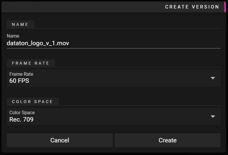
It is possible to adjust the following asset properties:
- Video
- Frame rate
- Color Space
- Image
- Color Space
DYNAMIC ASSET PROPERTIES
In this section we outline the asset properties for dynamic assets.
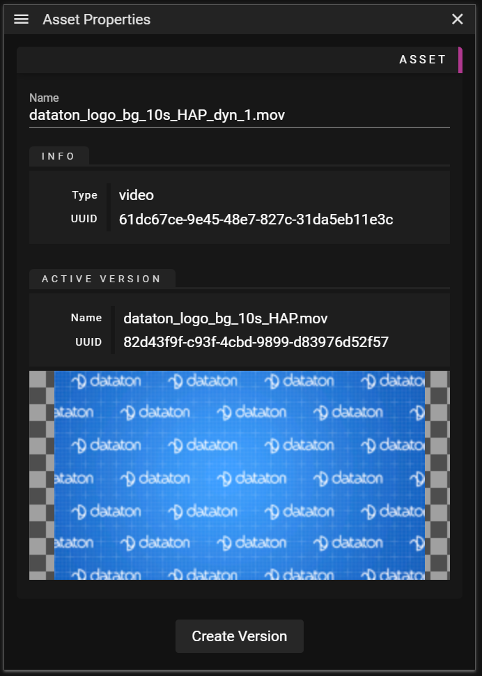
Below the general infomration you can find information about the asset that is currently active:
- Active Version
- Name is the name of the asset that is currently active.
- UUID is a universal unique identifier for the asset that is currently active.
- Preview displays a preview of the asset that is currently active.
SHAPE ASSET PROPERTIES
This section covers the properties for shape assets. The example below shows a text shape:
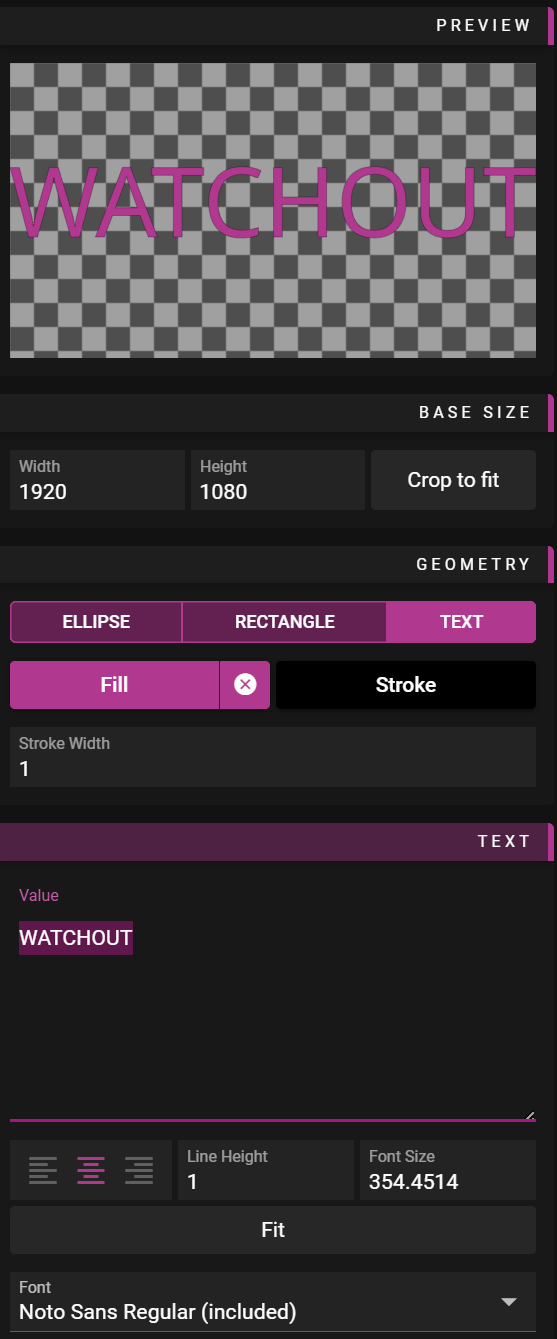
When a shape is created, it is wrapped inside a dynamic asset, which means some dynamic asset properties will also be shown.
Below that, you'll find information about the actual shape:
Preview
A visual preview of the shape appears at the top of the properties panel.
Base Size
This defines the size of the canvas (SVG viewbox) you are editing:
- Width - Canvas width in pixels
- Height - Canvas height in pixels
- Crop to Fit - Reduces the canvas size so the content fills it completely
Geometry
- Shape Type - Choose between rectangle, ellipse, or text
- Fill - Defines the shape's fill color
- Stroke - Sets the outline color
- Stroke Width - Sets the width of the outline in pixels
Text
These properties only appear when Text is selected as the Shape Type:
- Value - The text to display (can be multi-line)
- Text-alignment - Left, Center, or Right alignment
- Line-Height - Controls the spacing between lines
- Font Size - Sets the size of the text
- Fit - Automatically adjusts font size to fit within the Base Size
- Font - Displays and lets you select from available fonts
NOTE: WATCHOUT includes one default font. For more options, add your own fonts to the Asset Manager as regular assets. Once added, they will appear in the font selection dropdown.
WATCHOUT 7: Supported Media Formats Guide
Video Formats
WATCHOUT 7 features a media optimization system that converts input formats to optimized playback formats.
Input Video Container Formats
- MP4/MOV (QuickTime/MPEG-4)
- MXF (Material Exchange Format)
- MPG/MPEG (MPEG-1, MPEG-2)
- TS/M2TS (Transport Stream)
Input Video Codecs
WATCHOUT 7 can ingest these video codecs:
-
HAP Family
- HAP (standard)
- HAP Alpha (with transparency)
- HAP Q (higher quality)
- HAP Q Alpha (higher quality with transparency)
- HAP Alpha Only (transparency channel only)
- HAP R (BC7 texture compression)
-
Notch Family
- Notch LC (opaque)
- Notch LC Alpha (with transparency)
-
ProRes Family
- ProRes 422 (standard)
- ProRes 422 Proxy (lightweight)
- ProRes 422 LT (light)
- ProRes 422 HQ (high quality)
- ProRes 4444 (higher quality)
- ProRes 4444 Alpha (higher quality with transparency)
- ProRes 4444 XQ (extreme quality)
- ProRes 4444 XQ Alpha (extreme quality with transparency)
-
Other Codecs
- AVC/H.264
- HEVC/H.265 (8-bit)
- HEVC/H.265 10-bit
- MPEG2
NOTE: AVC/H.264 only supported up to level 5.2
-
Images (Raw formats)
- Raw 8-bit RGB
- Raw 8-bit RGBA (with transparency)
- Raw 16-bit RGB
- Raw 16-bit RGBA (with transparency)
- Raw 8-bit Y (luminance only)
Optimized Output Codecs
The system optimizes media to these playback formats:
-
GPU-Accelerated Formats
- HEVC (H.265)
- HEVC 10-bit (for HDR content)
- HAP
- HAP Alpha
- HAP Q
- HAP Q Alpha
- HAP Alpha Only
- HAP R
- Notch LC
- Notch LC Alpha
-
Raw Output Formats
- Raw 8-bit RGB
- Raw 8-bit RGBA (with transparency)
- Raw 10-bit RGB
- Raw 11-bit YUV 4:2:0
Audio Formats
WATCHOUT 7 provides comprehensive audio support for versatile sound design.
Input Audio Container Formats
- WAV (Waveform Audio)
- AIFF (Audio Interchange File Format)
- MP3 (MPEG Audio Layer 3)
- MP4/M4A (MPEG-4 Audio)
- FLAC (Free Lossless Audio Codec)
- OGG (Ogg Vorbis)
- AAC (Advanced Audio Coding)
Input Audio Codecs
-
Uncompressed
- PCM 16-bit
- PCM 24-bit
- PCM 32-bit float
-
Compressed Lossy
- MP3 (various bitrates)
- AAC (various profiles)
- Vorbis (OGG)
- WMA
-
Compressed Lossless
- FLAC
Playback Support
-
Sample Rates
- 44.1kHz (CD quality)
- 48kHz (professional standard)
- 96kHz (high resolution)
-
Channel Configurations
- Mono
- Stereo
- 5.1 Surround
- 7.1 Surround
- Multi-channel (up to 64 channels)
Image Formats
WATCHOUT 7 supports a wide range of image formats for high-quality still graphics.
Input Image Formats
-
Raster Formats
- PNG (with transparency)
- JPG/JPEG (lossy compression)
- TIFF (including multi-page)
- TGA (with alpha channel)
- BMP (uncompressed bitmap)
- GIF (no-animation)
- WEBP (next-gen format)
-
High Dynamic Range
- EXR (OpenEXR)
- HDR (Radiance)
-
Professional Formats
- PSD (Photoshop layers)
-
Vector Formats
- SVG (Scalable Vector Graphics)
-
Sequences
- Numbered image sequences (any supported format)
Optimized Output Formats
All images are regarded as raw input from a mapping perspective. Most images are 8bit per channel. But Tiff, for example is 16 bit per channel. So to change how images are ingested, change its raw format
Choosing the Right Codec
For Maximum Performance
- HAP Family: Hardware-accelerated, ideal for multi-display setups
- HAP Alpha/HAP Q Alpha: When transparency is needed
For Storage Efficiency
- HEVC/H.265: Smallest file sizes, good for long-duration content
- HEVC 10-bit: For HDR content with efficient storage
For Highest Quality
- Notch LC: High quality with good performance
- Raw Formats: Maximum quality for critical applications
For Transparency
- HAP Alpha: Best performance with transparency
- Notch LC Alpha: High quality with transparency
- Raw 8-bit RGBA: Uncompressed with transparency
By selecting appropriate formats, you'll achieve the optimal balance between visual quality, system performance, and storage efficiency in your WATCHOUT 7 productions.
ASSET MANAGER WEB USER INTERFACE
You can access the Asset Manager directly via the network by using a standard web browser and connecting to the Asset Manager on port 3023.
WEB ADDRESS
To access the Asset Manager running on the local computer, type the following in the web browser address field:
HTTP://localhost:3023
or
HTTP://127.0.0.1:3023To access the Asset Manager running on a remote computer with the IP-number 192.168.0.100, type the following in the web browser address field:
HTTP://192.168.0.100:3023
WEB VIEW
Once connected to the Asset Manager, you will see a list of all assets and folder in the Asset Manager.

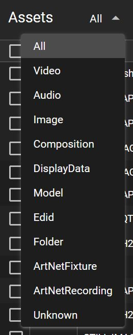 1. Assets list This is a drop-down list with the asset types to be viewed in the web UI.
Default is All but any single type of asset can be selected, for example Video, Audio, Image etc.
1. Assets list This is a drop-down list with the asset types to be viewed in the web UI.
Default is All but any single type of asset can be selected, for example Video, Audio, Image etc.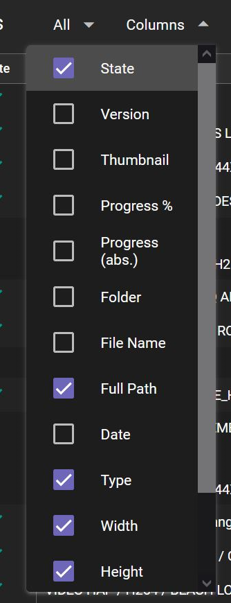 2. Columns This is a drop-down list to select which column to show for each listed item. Multiple columns can be selected for a more customized view.
3. Search field You can search for an asset in the database by entering a complete word, or part of a word, in its name. You can also search for a specific file extension, for example jpg.
4. Upload files Clicking on the icon will open a file dialog to add a specific file to the asset database.
5. Upload folder Clicking on the icon will open a file dialog to add a folder containing files to the asset database.
6. Create folder Clicking on the icon will create a new folder in the asset database.
Folder Views
- Clicking any segment inside of any of the asset paths will change the view to show only the assets in this particular folder and the asset paths will be relative to the selected view.
- The currently selected view is represented by a path in the top left corner (hidden by default).
- You can go back up the file hierarchy to any of the parent folders by clicking a segment in this path.
ADDING ASSETS IN WEB UI
You can add assets to the Asset Manager in two ways:
-
By clicking the two icons top right, Upload files or Upload folder. Both these buttons will open a file dialog allowing you to select a single file or a folder containing multiple files to be added to the Asset Manager.
-
By selecting the files or folders from a open file window and drag-dropping them to the Asset Manager web UI.
After the file/folder is added, the files will be optimized and imported to the Asset Manager database and there will be a visible progress bar indicating the status of the import/optimization.
DELETING ASSETS IN THE WEB UI

Click the checkbox (1) next to the file or folder to be deleted. Click the Delete (2) button in the lower right corner to delete the selected items. Note: This action cannot be undone.
WARNING
-
Be careful when you delete an asset! The system does not check if the asset is used in an old or currently loaded show. It is the user's responsibility to ensure that a used asset is not deleted.
-
Deleting a folder will also delete all assets inside the folder.
-
You cannot undo the deletion of a folder or an asset in the web UI.
ASSET WATCHER
The Asset Watcher is a service whose sole purpose is to detect when the contents inside a user-specified folder change, and then upload that file/folder to the Asset Manager.
GETTING STARTED
The easiest way to get started with the Asset Watcher is to configure it directly from Producer. To access the Asset Watcher user interface, open the Devices window, select your local node and click the Asset Watcher button found in the Actions section of the Nodes.
You can only configure the Asset Watcher running on your local machine/node, ie, the machine running Producer. The ensures that the owner of a node decides what files are being shared from that node.
The Asset Watcher requires the following:
- One or more folders tracked by the Asset Watcher.
- One Asset Manager to which the tracked/watched files are uploaded.
- You may only set a single Asset Manager to upload assets.
- Read more about the reason behind this limitation here.
- You may only set a single Asset Manager to upload assets.
Below is a short video demonstrating how to set up a Asset Watcher in a few clicks.
To set up an Asset Watcher :
- Locate and click on the Asset Watcher button in the Node Properties window.
- Set the Target Asset Manager.
- Set one Watch Folder on the local machine.
- Start the Asset Watcher by clicking the heart icon.
- Note the Asset Watcher icon showing up in the Devices window.
To disable the Asset Watcher, open the Asset Watcher dialog again and click the heart icon.
STARTUP
When the Asset Watcher is started the following actions occur:
- The folder structure on the target Asset Manager is recreated inside the folder being watched.
- This provides an overview of what is already on the target Asset Manager.
- It also reduces the risk of accidently misspelling the intended asset path for assets you want to upload.
- This provides an overview of what is already on the target Asset Manager.
- All files (and folders) inside the folder being watched are uploaded, provided they have:
- Changed since they were last uploaded.
- Not been uploaded before.
Example:
- There is a single folder being watched and it is located here: "C:/watched"
- Note: No Asset Path has been set.
- The target Asset Manager has the following folder structure:
- videos
- images
- audio
During the Asset Watcher startup:
- The following folders will be created (provided they do not already exist).
- C:/watched/videos
- C:/watched/images
- C:/watched/audio
- All files already in "C:/watched/" will be uploaded to the target Asset Manager.
ASSET PATH
To add a folder to watch:
- Select the folder on your local machine.
- Select an Asset Path to indicate where to map that folder.
- The Asset Path can be left blank.
- This means that assets will be uploaded to the root of the Asset Manager.
- The Asset Path can be left blank.
Example:
- There is a single folder being watched and it is located here: "C:/watched"
- The target Asset Manager has the following folder structure:
- videos
- draft
- final
- videos
The goal is to upload the assets inside "C:/watched" to "videos/draft". This can be done by setting the Asset Path to "Videos/Experimental" in the Add Watch Folder dialog.
This can also be achieved by leaving the Asset Path blank and letting the Asset Watcher create the Asset Manager folder structure inside the "C:/watched" on startup, then making sure to add the experimental videos to "C:/watched/videos/draft".
Think of the Asset Path setting as an optional way to restrict/map the upload to a specific location.
COMMAND PROMPT
It is recommended to configure the Asset Watcher from Producer but you may also configure it from the command prompt. This may be useful if you have a machine which is not running Producer and you still want to share content from it.
To start the Asset Watcher from a command prompt:
- Open a command prompt.
- Navigate to the folder where the asset-watcher.exe is located.
- Start the Asset Watcher by typing:
- asset-watcher.exe -i
-f - asset-watcher.exe -i "192.168.0.12" -f "C:/watched"
- asset-watcher.exe -i
It is possible to start the Asset Watcher with folders being mapped to specific **Asset Path**s as well. This can be done by using the "->" syntax. For instance by typing:
- asset-watcher.exe -i "192.168.0.12" -f "C:/watched -> videos/draft"
For more information about ways to configure the Asset Watcher from a command prompt you can type:
- asset-watcher.exe --help
RESERVED FILE/FOLDER NAMES
There are some file and folder names that instruct the Asset Manager on how the file/folder is to be used:
- If you create a folder named <user selected name>_dyn_<type> it will create a dynamic asset on the Asset Manager.
The <type> can be any of the following:- visual
- audible
- display
Valid examples: - a_dyn_visual
- b_dyn_audible
- c_dyn_display
- If you add files inside that folder these assets will become versions handled by the dynamic asset.
- If you create a folder named <user selected name>_imgseq the _Asset Manager will interpret the contents of that folder as an image sequence. Images added to that folder will be converted to a video.
- It is possible to patch image sequences by replacing an image in the <user selected name>_img_seq folder (see bullet above).
- It is possible to patch a video by adding a new video file containing the frames you want to patch.
- If you have a video named awesome.mp4 you can patch this by adding another file named awesome-1000.mp4.
- This will insert the frames of awesome-1000.mp4 at frame 1000 of awesome.mp4.
- There is no way to specify a frame range, only the starting frame. This means that the entire contents of awesome-1000.mp4 will be inserted into awesome.mp4.
- If you have a video named awesome.mp4 you can patch this by adding another file named awesome-1000.mp4.
LIMITATIONS
There are some limitations to how the Asset Watcher can be used and how it works.
- Folders being watched cannot overlap each other.
- Watching two sibling folders is possible, for example:
- "C:/watched" and "C:/watched2"
- Watching two folders organized like this is not possible:
- "C:/watched" and "C:/watched/videos"
- Watching two sibling folders is possible, for example:
- There can only be a single running Asset Watcher process per node.
- This ensures there is no overlapping of folders being watched.
- Deleting an asset file/folder inside a watch folder will not delete the asset on the target Asset Manager.
- Moving an asset file/folder inside a watch folder will not move the asset on the target Asset Manager.
- If a file/folder is moved a new asset will be created on the target location.
Asset Transfer
Overview
Efficient transfer of assets is a vital component in WATCHOUT 7. The system provides several methods to move media between computers in your production network.
Security
To protect your system, WATCHOUT 7 requires explicit permission to access folders for asset transfers.
A file called
allow_list.jsonmust be placed in the same folder as your wo7_settings to define which folders are accessible.Example content of allow_list.json:
{
  "folders": ["C:/", "D:/shared/watchout/", "D:/shows/arr/assets"],
  "update_allowed": true
}
The
update_allowedfield enables remote software updates on this node. See Software Update Allowlist for details.NOTE: On WATCHPAX systems, the allow_list is pre-configured for you.
Transfer Modes

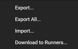
Export
- Export - Export the selected asset to any computer
- Export All - Exports the full database to any computer
You can update an export by adding files. It will always do as little as possible, so you can add the same assets many times, without getting a bigger export file
Import
Imports to current Asset Manager from any computer
No asset transfer will happen if the assets to import already are on the Asset Manager. Doing multiple imports of same assets takes almost no time.
Download to Runners
This is an export. But to multiple Nodes. It updates the Runner Cache the selected nodes so data is there when you start working on your show.
Do this when the runner is not running a show. Otherwise it will interfere with normal show asset caching.Create Archive...
On the File menu you can choose to archive current show. This is done to a folder and will contain:
- .watch file
- Settings and layout files
- A normal export folder containing all assets in the show
The export folder is the same as any transfer folder. Therefore you can update the content of show files and exports.
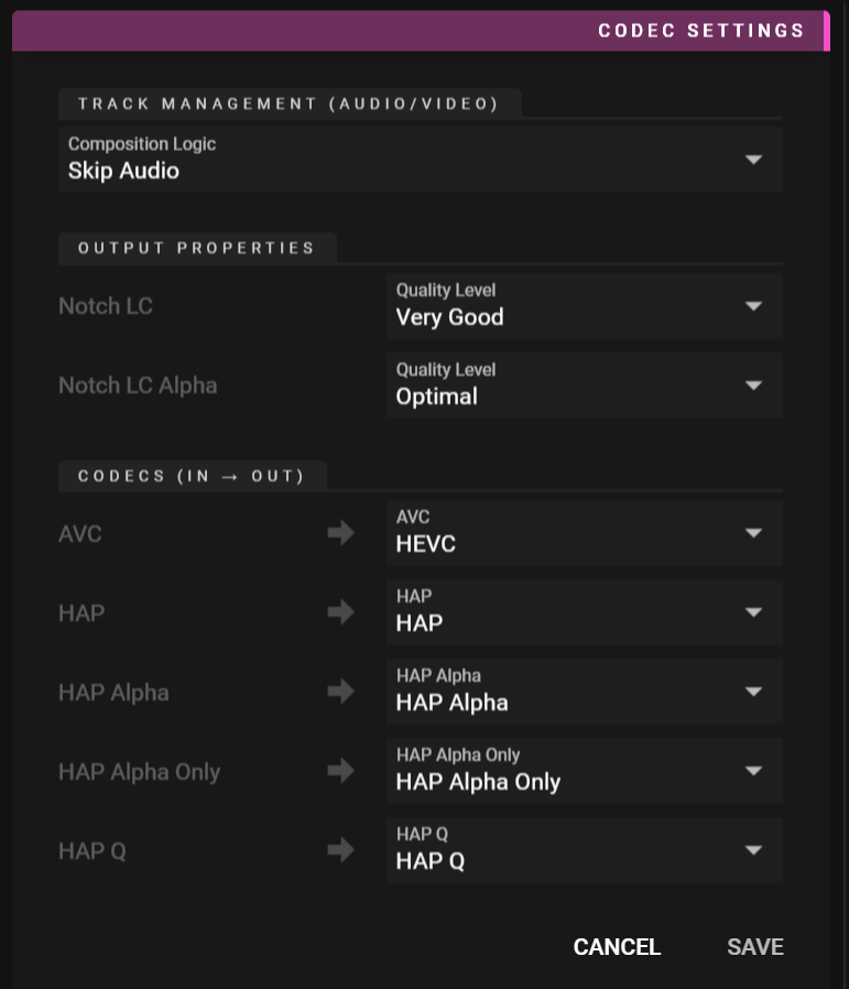
ASSET MANAGER SETTINGS
The Asset Manager Settings can be accessed from the Asset Manager menu.
Setting up codec mappings in advance is necessary because WATCHOUT doesn't know what codecs are in the files until they're imported.
Settings Dialog
Bandwidth Limit
Limits the network bandwidth used when transferring assets. Set in Mbit/s. Use 0 for unlimited bandwidth.
This is useful when sharing network infrastructure with other systems or when you need to avoid saturating slower network links.
Track Management
Here you decide what to do with files that have both audio and video. You have 4 options:
- Skip Audio - Recommended if you do not want audio in most cases
- Skip Video - Only audio is imported
- Composition - Aligns video and audio playback
- Individual Assets - You get two different assets
NOTE: If you plan to drag assets to stage or timeline, choose one of the two first options.
Using Composition may give you surprising results, as Audio and Video may not start at the same time.Notch quality levels
- Good
- Very Good
- Excellent
- Optimal
- Best
We recommend optimal for most use cases.
Codecs (In -> Out)
Here you can change how In formats gets mapped to WATCHOUT by changing the by changing the Out format.
You can find more information about formats and codecs here.
TIP: Images are treated as raw input. In order to remap Images, you have to change the raw output types
TIMELINES & CUES
In this chapter you will learn about what a Timeline is and how you can use cues to populate your Timeline(s) with content.
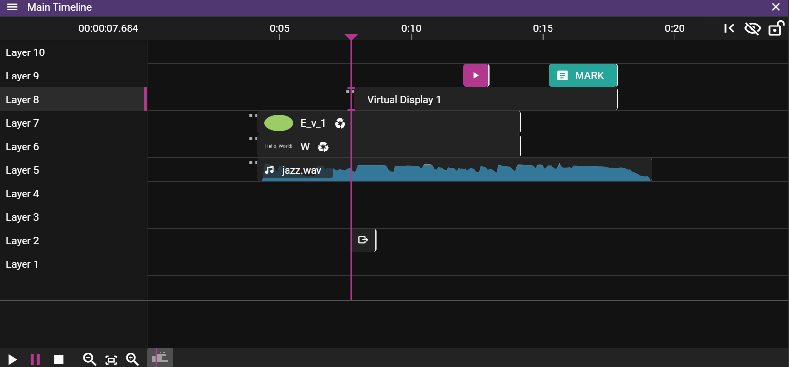
TIMELINE
A Timeline is where you place the content that you want to play to your audience. The content, like videos or audio, is defined in assets and by dragging an asset to a Layer on the Timeline you create cue. By selecting a cue on the timeline you can further edit how the referred asset is used in the show. For instance, you may want to change the duration of a video clip or you may want to add an Effect.
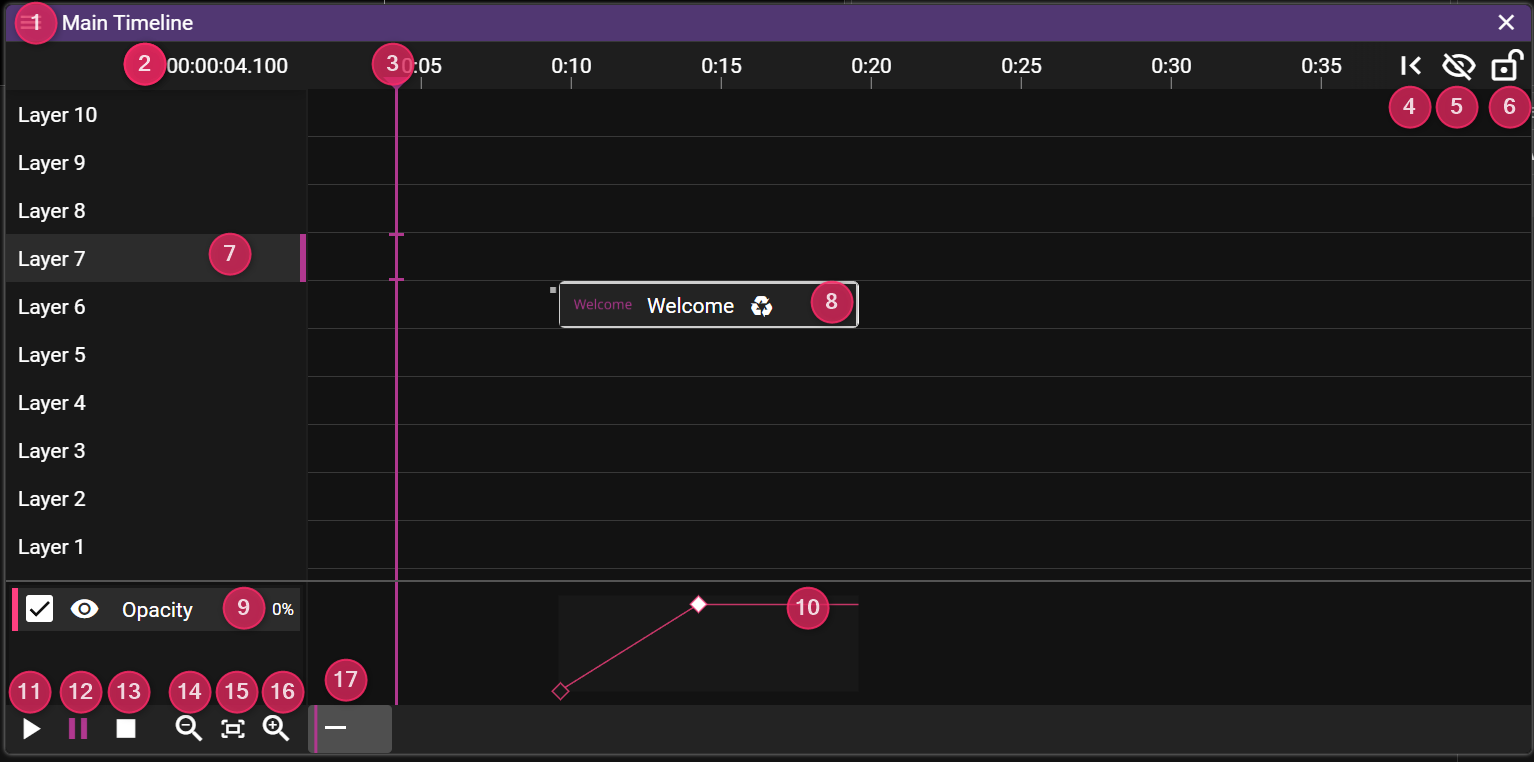
- Name shows the name of the Timeline.
- Timeline Time shows where the Time Position Indicator is located.
- Edit this to jump to a specific time.
- Time Position Indicator shows the current time position using a vertical line drawn through the Timeline window. The color of the line indicates the Click Jumps to Time state.
- Jump button to jump to last start position on the Timeline.
- Blind Edit button can be used to enter blind edit mode for the timeline.
- LOCK STATE Can be open, locked for edit, or hands off (you cannot move the play marker)
- Active Layer shows a pink vertical bar to convey that this layer is active.
- Cue object that can be selected to edit show content.
- Effects shows the chosen effects for the selected cue.
- Use the eye to hide/show a specific effect curve.
- Tween Curve allows you to create and edit tween points.
- Play button to start playback.
- Pause button to pause playback.
- Stop button to stop playback.
- Zoom Out button to zoom out the Timeline view.
- Zoom To Fit Zoom in to fit timeline, or selected cues (Ctrl-0)
- Zoom In button to zoom in the Timeline view.
- Horizontal Scrollbar to scroll to a specific time in the Timeline view.
Tip 1 To change timeline time (3) using keyboard, press t.
Tip 2: A nice feature is the Insert/Delete Time function (Ctrl+Shift+T). This allows you to add or remove time at the play marker position. It includes options to exclude updating cues or tween points. This feature is a lifesaver when directors demand "just five more seconds here" or "trim that boring part!"
Tip 3: Use Ctrl+0 to zoom to fit. If cues are selected, it zooms to fit the selection. Otherwise, it zooms to fit the entire timeline.
TIMELINE CONTEXT MENU
There are two context menus in the Timeline window, one for editing the timeline itself and one for working with cues.
TIMELINE GENERAL CONTEXT MENU
If you right-click in the Timeline window, without having any cue selected, you will open the general context menu.
You can also open this menu by clicking on the three horizontal lines in the top left corner of the Timeline window.
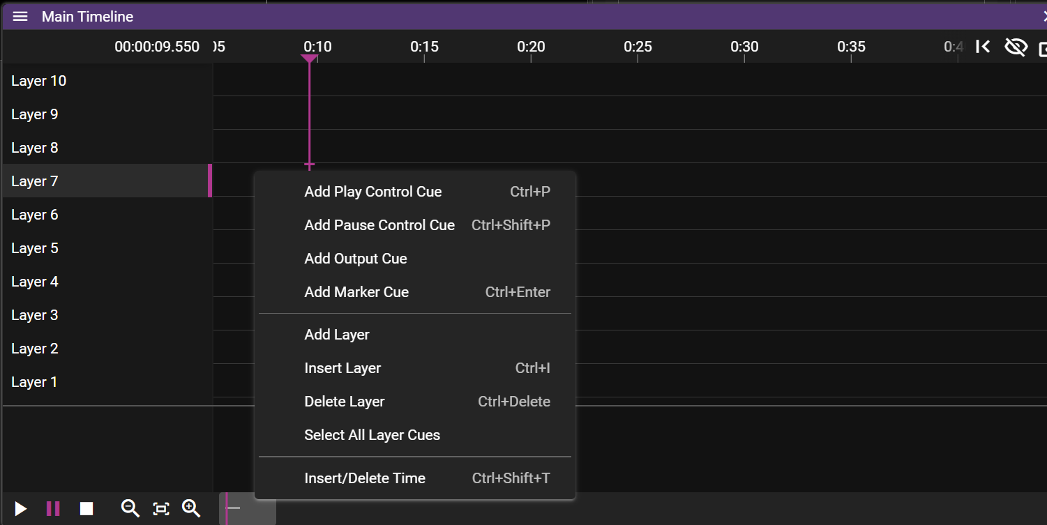
- Cue operations:
- Add Play Control Cue adds a play control cue.
- Add Pause Control Cue adds a pause control cue.
- Add Output Cue adds an output control cue.
- Add Marker Cue adds a marker cue.
- Layer operations:
- Insert Layer inserts a layer above the active layer.
- Add Layer adds an additional layer at the top of the Timeline.
- Delete Layer deletes an additional layer at the top of the Timeline.
- Select All Layer Cues selects all cues on the active layer.
- Insert/delete time Adds or remove time from the timeline
TIMELINE CUE CONTEXT MENU
If you right-click in the Timeline window, while having one or multiple cues selected, you will open the cue context menu.
You can also open this menu by clicking on the three horizontal lines in the top left corner of the Timeline window. Again, at least one cue needs to be selected for this menu to be shown.
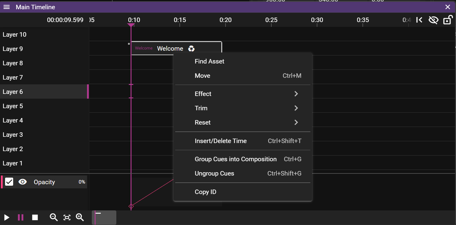
- Find Asset tries to find the asset(s) associated with the selected cue(s).
- The asset(s) found will be selected in the Asset Manager window.
- Move opens a dialog that allows you to move the selected cue(s).
- Effect opens a sub menu allowing you to add or remove effects to the selected cue(s). See Effects for details.
- Trim allows you to shorten the duration of the selected cue(s) based on where the Time Position Indicator is located.
- Start edit the start time of the cue.
- End edit the end time of the cue.
- Reset allows you to reset some settings.
- In-Time.
- Duration resets the duration of the selected cue(s) to the original duration.
- Group cues into composition creates a composition.
- Ungroup cues removes the composition.
- Copy ID copies the timeline/cue IDs. Handy for use with the external protocol.
LAYERS
A Timeline consists of multiple layers on which cues can be added. When the show is empty you can think of the layers in the Timeline as a stack of fully transparent papers. As you add image or video cues to the layers you will fill these transparent "papers" with pixels. The layer with the highest number represents the top of the "paper" stack which means that cues placed on this layer will render on top of cues placed on layers below it. You may override this behaviour by changing the Stacking on the cue.
Layers further up the layer stack may occlude cues further down:
If a cue is selected on the timeline it will be prioritized for movement operations in the Stage window:
KEYING LAYER
From the Layer Properties, which you access by clicking on a layer name in a Timeline, you can turn the layer into a keying layer which means that all cues that are present on that layer are used to produce a key. You can think of the key as a filter which is used to mark areas which you want to fill with specific content. For instance, you may place a circular shaped image on a keying layer and have that circle being filled with contents from cues residing on regular layers.
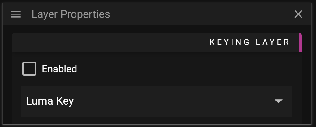
WATCHOUT provides four different types of keying layers. Each type uses a specific pixel property to define how the keying filter is created. Note that the keying layer type only affects the cues residing on the keying layer and tells the system how these cues are interpreted to create the keying filter. The following keying filter types are available:
- Luma Key means that the luma value of each pixel is used to define the filter.
- Luma Key (Inverted) means that the inverted luma value of each pixel is used to define the filter.
- Alpha Key means that the alpha value of each pixel is used to define the filter.
- Alpha Key (Inverted) means that the inverted alpha value of each pixel is used to define the filter.
If you define multiple keying layers, even on different timelines, all the cues on these layers are combined into a single keying filter. Each cue will contribute to the keying layer according to the keying layer type active on the layer on which they reside.
The layer order of the keying layers does not matter, you are free to place the keying layers where it is most convenient to you.
As outlined above you may use keying layers to define how you mark pixel areas based on their properties, but once you have created these pixel areas you want to define what content you should fill those pixels with. You may read more about how this is done in the Key & Fill section found in the Cue Properties.
You can read more about this effect here.
CUE HOVER INFO
When you hover over a cue some helpful information will be shown in the top of the Timeline:
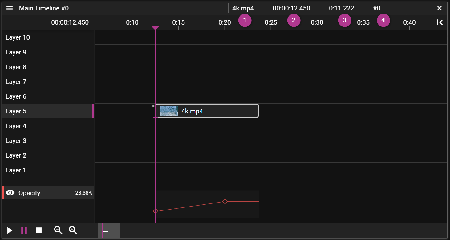
- The name of the media applied to the cue.
- The Timeline time when the cue starts.
- The duration of the cue.
- The cue ID.
CUE OVERLAPS
When two cues reside on the same layer they may overlap. This is usually an unwanted state so when an overlap has been detected the affected cue objects, in the Timeline, are marked with a striped pattern. This can be resolved by selecting and moving cues until the pattern disappears.
Not all cue overlaps are forbidden. Media cues may have overlapping cues of the following types:
There is also another exception where cue overlaps are allowed and that is when you are using Fade-in/out as shown in the video below:
DISABLED CUES
Cues can be disabled to temporarily exclude them from playback without deleting them. Disabled cues are shown with a grey striped overlay and reduced opacity, making them easy to identify on the timeline.
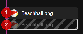
- Normal cue
- Disabled cue
To disable a cue, set its condition to Disabled in Cue Properties.
TIME POSITION INDICATOR
The Timeline Position Indicator shows the current time position using a vertical line drawn through the Timeline window. Its color indicates if the Click Jumps to Time is active. If it is active it means that when a cue is selected the Timeline Position Indicator will jump to the start of the cue.
The Timeline Position Indicator is drawn as a solid pink line if Click Jumps to Time is active, otherwise it will be drawn as a dashed purple line.
CUE TRIM
This feature allows you to change the duration and starting/end frame of the referred asset based on where the Time Position Indicator is located. You can think of it as cutting out parts of the start or the end of a video or audio clip. When you trim a cue using Start the In-time property is changed.
BLIND EDIT
Blind edit mode lets you make changes to a Timeline without instantly reflecting them on the runners.
Click the slashed eye button in the top right corner of the Timeline window to enter blind edit mode. A copy of the Timeline appears with a green frame, also shown in the Stage window. While editing, the Stage only shows your blind edit changes—the original show continues playing on the runners in the background. When ready, click the check button to apply your changes. A confirmation dialog appears before the changes are propagated to the runners.
The link button moves the Time Position Indicator to the current time of the original Timeline.
NOTE: Control cues do not work in blind edit mode to prevent affecting other timelines.
TIMELINE PROPERTIES
In this chapter you will learn about the available Timeline Properties.
GENERAL
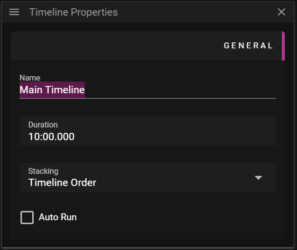
- Name defines the name of the Timeline.
- Duration defines the duration of the Timeline.
- This input field supports using a letter to define the unit of the inputed value:
- s/seconds for seconds.
- m/minutes for minutes.
- h/hours for hours.
- This input field supports using a letter to define the unit of the inputed value:
- Stacking defines the render order of content from different timelines.
- Timeline Order uses the order in which the Timelines are listed in the Timelines window window.
- Always on Top means that the content of this Timeline will render on top of other Timeline(s).
- Clarification: Always on Top is always rendered on top of Timelines using the Timeline Order. If multiple Timelines are using Always on Top the order in which Always on Top was activated will decide the render order. The Timeline that activated Always on Top most recently will be the topmost Timeline.
- Auto Run can be activated to make the timeline start playing automatically once the Director has loaded the show.
TRIGGERS
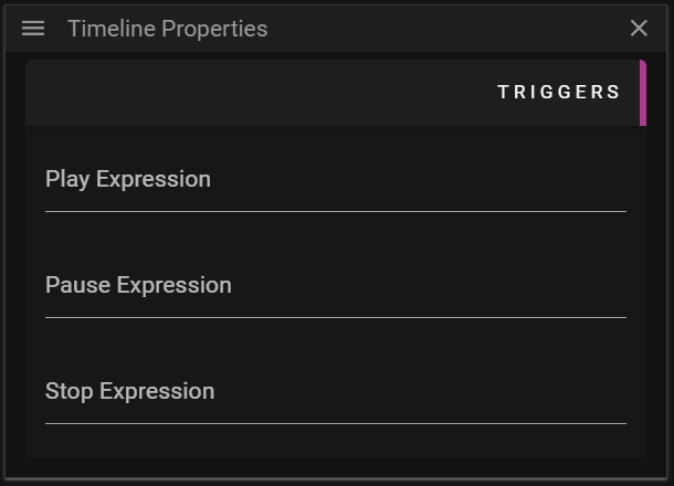
- Play Expression defines an expression that can trigger play.
- Pause Expression defines an expression that can trigger pause
- Stop Expression defines an expression that can trigger stop
You can read more about expressions here.
FAQ
Q. Which Timeline is rendered on top if multiple Timeline(s) uses Always on Top?
A. If multiple Timelines uses Always on Top the order in which Always on Top was activated for the Timeline will decide the render order.
-
For instance, let us assume you have three Timeline(s) called A, B and C, each with Stacking set to Timeline Order.
- You set Always on Top for A.
- This means that A will render on top of B and C. The render order for B and C is still decided by the Timeline Order.
- Later on you set Always on Top for B.
- This means that B will now render on top of A (since it was changed after A).
- Note that A will still render before C since Always on Top is always rendered on top of Timeline(s) using the Timeline Order.
- You set Always on Top for A.
TIMELINES
Producer supports having multiple timelines. These timelines are organized in the Timelines window.
Using multiple timelines can be useful in a number of situations, for instance if you want to play specific content on demand.
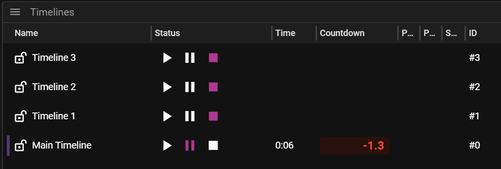
- Name shows the name of the timeline.
- Status shows whether the timeline is played, paused or stopped.
- Time shows the time the timeline is currently at.
- Countdown count down to next marker cue
- Play Expression expression that trigger play.
- Pause Expression expression that trigger pause.
- Stop Expression expression that trigger stop.
- ID timeline id
Tip The purple line at the row start indicates the timeline that will receive playback keypresses
TIMELINES CONTEXT MENU
You can access the Timelines context menu by right-clicking in the Timelines window. You can also open this menu from by clicking on the three horizontal lines in the top left corner of the Timelines window.
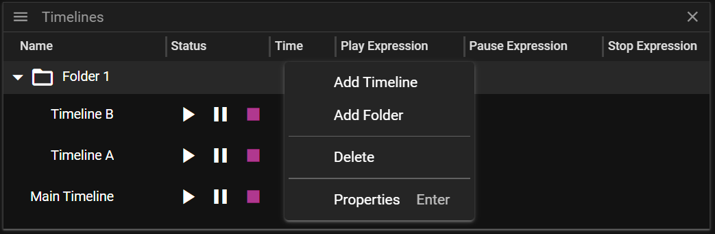
- Add Timeline adds a new timeline.
- Add Folder adds a new folder.
- Delete deletes the selected Timeline(s).
- Properties activates and shows the Timeline Properties window.
TIMELINE AND FOLDER COLORS
Timelines and folders can be assigned colors to help organize your show. Set the color in Timeline Properties or Folder Properties.
- Timeline colors appear as a tint on the timeline header and in the Timelines list
- Folder colors are inherited by timelines within that folder (unless the timeline has its own color)
- Use colors to group related timelines (e.g., all intro sequences in blue, all loops in green)
FAQ
Q. What is the benefit from using multiple timelines? Why cannot I just add another layer?
A. Multiple timelines give you the possibility to organize your show into smaller chunks with descriptive names. It also allows you better control over when specific content should be played.
CUE
A cue is an object that exists on a layer in a Timeline. To create a cue you simply drag an asset from the Asset Manager to a layer on the Timeline. This will create a placeholder for the asset, the cue, that can be used to edit how the content of the asset is being used in a WATCHOUT show.
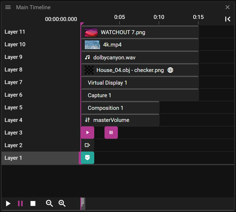
WATCHOUT supports the following cue types:
- Image
- Video
- Audio
- 3D Model
- Virtual Display
- Capture
- Composition
- Variable
- Control
- String Output
- Art-Net Output
- Art-Net GDTF Output
- Art-Net Recording Output
- Marker
When a cue is selected on the Timeline or in Stage, the Cue Properties window becomes active.
If the Time Position Indicator overlaps the cue, and the cue refers to something visual, it will be shown in the Stage window.
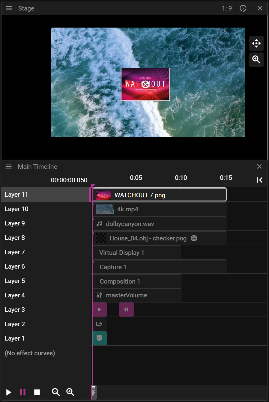
CUE TYPES
In this section we cover the cue types you can use to build WATCHOUT shows.
MEDIA CUES
A cue that produces pixels or audio is referred to as a media cue. The word media cues are used in the documentation to explain concepts that are common for these cues.
The following cues are considered to be media cues:
IMAGE CUE
A cue that refers to an image asset like a .png or .psd file.
VIDEO CUE
A cue that refers to a video asset like a .mp4 or .mov file.
AUDIO CUE
A cue that refers to an audio asset like a .wav file.
3D MODEL CUE
A cue that refers to a 3D model asset like a .obj file.
You can read more about 3D models here.
VIRTUAL DISPLAY CUE
A cue that is used to display content recorded by a virtual display. To create a virtual display cue:
- Right-click the Stage window and select Add Virtual Display.
- Drag the virtual display from the Devices window to a Timeline.
- Note that you can replay the recorded content on the surface of a 3D model. To do so you need to drop the virtual display on top of a cue referring to a 3D model/mesh.
Virtual display rendering does not come for free. To record content so that it can be replayed, the content must be rendered to an offscreen buffer on the GPU. This implies both more memory consumption and more rendering. Needless to say, you should use virtual displays with care to avoid severe performance penalties.
This cue supports the same properties as an image cue.
You can learn more about virtual displays here.
CAPTURE CUE
A cue that can be used to display data captured by a Capture Device. This cue supports the same properties as an image cue.
COMPOSITION CUE
A cue that consists of a group of cues defined on a Composition Timeline.
A composition cue makes it easy to re-use or re-arrange show sections or short snippets. It also makes it easier to apply the same effect to a group of media elements – for instance, to move and scale a set of images together.
There are two ways to create composition cues:
-
Primary approach:
-
- Select cues you want to group into a composition.
-
- Select Group Cues into Composition in the Producer/Timeline menu.
- Note that you may also disband a group into separate cues. This is done by selecting Ungroup Cues from the Producer/Timeline menu.
OR
-
-
3D model approach:
- Drop a 3D model asset containing multiple meshes to a Timeline or the Stage window.
- Each mesh is represented as a cue on a separate layer which gives the possibility to play different media (and effects) on each mesh.
To access the composition Timeline you can double-click on the composition cue. Note that this will only show what is present in the composition timeline, everything else is hidden.
Changes made to a composition, such as swapping a media cue, will automatically be applied across all instances of that composition on all timelines.
VARIABLE CUE
A cue that refers to a variable defined in the Variables window. Create this cue by dragging a variable from the Variables window to the timeline.
Select the cue and edit the Effect to configure how variable values change over time.
CONTROL CUE
A cue that can be used to trigger jumps in time and change playback state for one or multiple Timelines.
STRING OUTPUT CUE
A cue that gives you the possibility to send arbitrary data to a device on the network. The data is sent when the Timeline time reaches the cue Start Time.
You can read more about its properties here.
ART-NET OUTPUT CUE
A cue that gives you the possibility to send a single or ten-channel output via the Art-Net protocol. Data sent is controlled by the different Effect levels.
ART-NET GDTF OUTPUT CUE
A cue that gives you the possibility to send single or multiple channel output via the Art-Net protocol defined by the GDTF file used. Data sent is controlled by the different Effect levels.
ART-NET RECORDING OUTPUT CUE
A cue that gives you the possibility to send a recoded sequence of Art-Net channels that have been recorded with the WATCHOUT Art-Net Recorder. Data sent can be modified by using the different Effect levels.
MARKER CUE
A cue that can be used to simplify WATCHOUT show monitoring and control. It gives the user the possibility to define a description and countdown/countup labels.
CUE PROPERTIES
In this chapter you will learn about the available Cue Properties.
GENERAL
The General section allows you to edit common data such as Start Time and Duration.
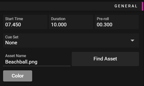
- Start Time defines when the cue starts playing.
- Color defines the color used for the cue on the Timeline.
- The main purpose is to make it easier to organize the cues used in your show.
- Lock can be activated to disable the possibility to edit a cue.
- Media cue-specific settings:
- Duration defines how long the cue will play.
- Pre-roll defines how far ahead of the cue's Start Time the referred media asset will be prepared by the media server (loaded from the disk etc).
- Cue Set defines what cue set the cue is part of
- Find Asset lets you local the asset in asset window
- Control and marker cue-specific settings:
- Name is a user-defined name for the cue. This can be useful when defining jumps in time.
PLACEMENT
The Placement section allows you to edit data related to the location of the cue in the Stage window.
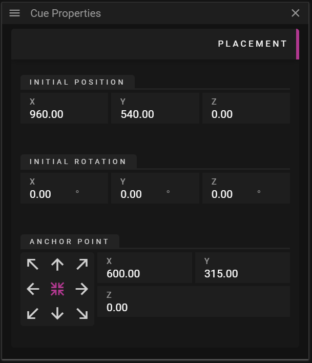
- Initial Position defines the position of the cue without any effects applied to it.
- Initial Rotation defines the rotation of the cue without any effects applied to it.
- Anchor Point defines a cue local point that does not move when scaling and rotating the cue.
- The anchor widget, with arrows, can be used to move the anchor point to the corners, edges or the center of the cue.
MEDIA PLAYBACK
The Media Playback section allows you to edit data related to looping and time offset for the referred asset.
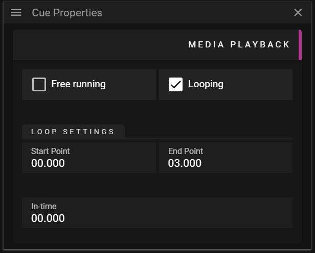
- Free Running activates the play state of the cue regardless of the Timeline play state.
- Looping activates looping of the referred asset.
- Start Point defines when looping will start in the referred asset.
- End Point defines when looping will end in the referred asset
- In-time defines the offset before the cue starts playing the asset in question.
- For instance, if you want to skip playing the first second of a video you can set this to one second.
Free running and looping changes the appearance of the cue:
- Free Running
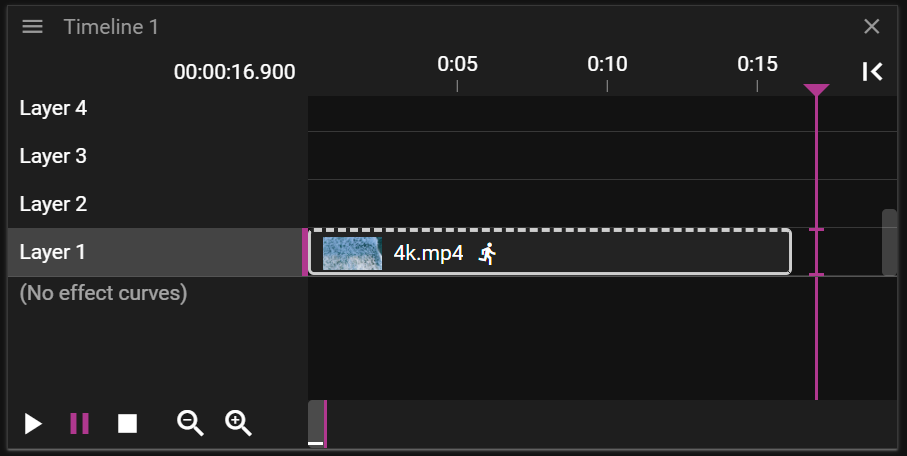
- Looping
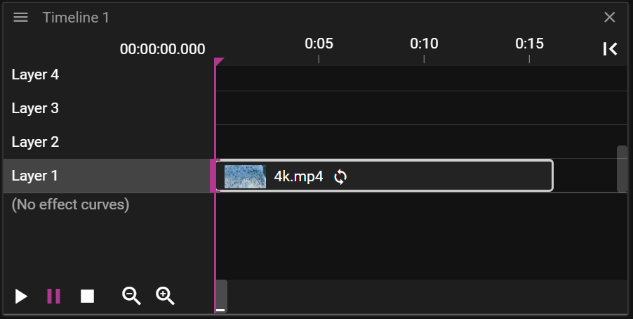
FADE IN/OUT
The Fade-in/out section allows you to edit how the referred asset gradually becomes visible (fade-in), from when the play state reaches the cue, and how it gradually becomes invisible (fade-out) until the play state reaches the end of the cue.
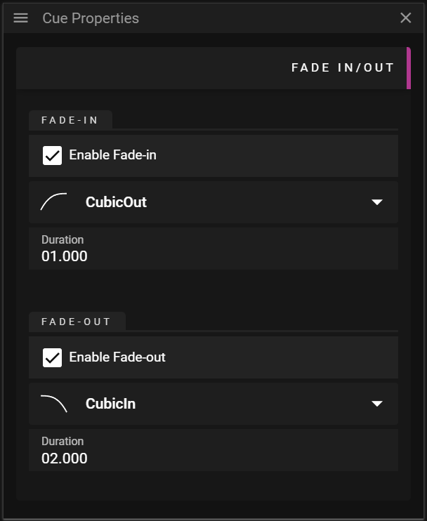
- Enable Fade-in adds a fade-in effect
- Enable Fade-out adds a fade-out effect
- Curve defines what curve to use for the effect.
- Duration defines the duration of the effect.
PRESENTATION
The Presentation section allows you to edit data related to rendering of the asset.
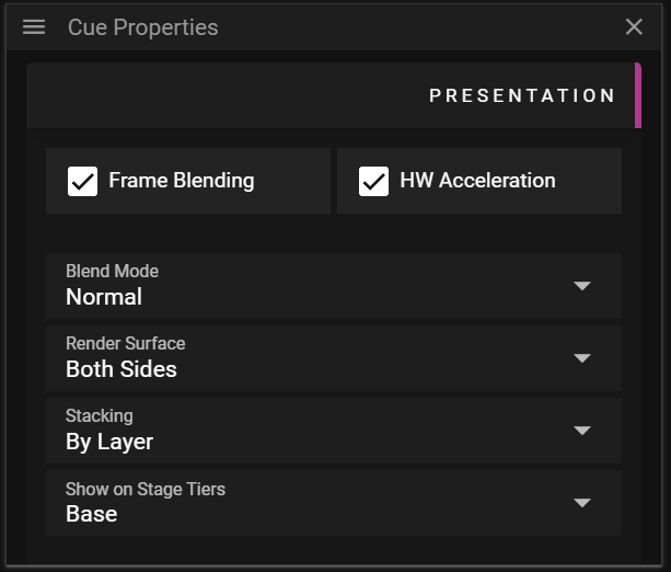
- Frame Blending activates smooth transitions between media frames.
- Note that it consumes more memory.
- HW Acceleration is used for decoding specific codecs, like HEVC.
- Depending on your system and scenario it may be more efficient to keep this deactivated.
- Blend Mode defines how cues using transparency are blended against what has already been rendered.
- Available options are Add, Multiply, Screen, Lighten, Darken and Linear Burn.
- Render Surface defines which parts of cue surface to render: Inside, Outside or Both Sides.
- This can be useful when handling 3D models that have inconsistencies related to the front and back side of its polygons.
- Stacking defines the order in which cues on the Timeline are rendered.
- By Layer means that the layer number defines the render order.
- Layer N is rendered before layer N + 1.
- By Z means that the cue surface depth, the distance to the camera, defines the render order.
- By Layer means that the layer number defines the render order.
- Show on Stage Tiers defines the tiers in which the cue will be rendered.
- A display may decide to only render cues belonging to a specific tier.
ASSET
The Asset section allows you to edit data related to the asset.
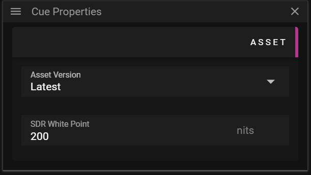
- SDR White Point defines the standard-dynamic-range white point in nits.
CHROMA KEY
The Chroma Key section allows you to enable chroma keying for a specific cue. Chroma is the degree of strength in a color.
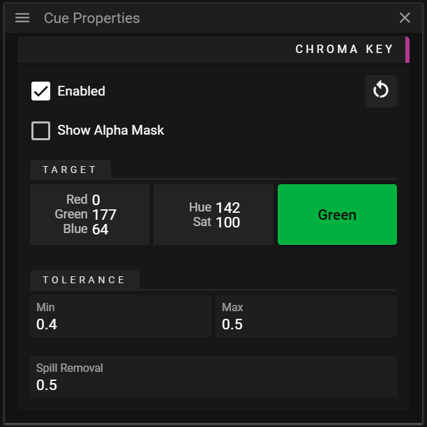
- Enabled toggles chroma keying on or off.
- Show Alpha Mask can be enabled to show which pixels that will be kept and pixels that will be dropped (filtered out).
- White pixels are kept (opaque).
- Black pixels are dropped (fully transparent).
- Red pixels are affected by the Spill Removal solution. You can read more about that below.
- Target defines the chroma that will be filtered out (hidden).
- Red channel.
- Green channel.
- Blue channel.
- Hue of the target chroma.
- Saturation of the target chroma.
- Color opens a color widget allowing you to define the target chroma.
- Tolerance defines how to handle chroma values that are close to the Target chroma in YUV-space.
- Min defines how far from the target chroma, in YUV-space, chroma values are considered to be fully transparent (completely hidden).
- The value defines the black circle, in YUV-space, shown in the image below.
- Chromas that are inside this circle will be fully transparent (hidden).
- This value should be below the Max value.
- The value defines the black circle, in YUV-space, shown in the image below.
- Max defines how far from the target chroma, in YUV-space, chroma values are considered to be fully opaque (not hidden at all).
- The value defines the white circle, in YUV-space, shown in the image below.
- Chromas that are between the black and white circle gradually change between fully transparent (at the border of the black circle) to opaque (at the border of the white circle).
- This value should be above the Min value.
- The value defines the white circle, in YUV-space, shown in the image below.
- Spill Removal is used to reduce chroma keying artifacts around the border between kept and dropped pixels.
- The value defines the red circle, in YUV-space, shown in the image below.
- Chroma values that are between the white and red circle, values inside the "spill ring", will be desaturated to reduce artifacts in this chroma range.
- The thickness of the "spill ring" is given by min (Max - Min, 0.1) * Spill Removal.
- At the border of the white circle the saturation is given by 1.0 - Spill Removal.
- At the border of the red circle the saturation is 1.0.
- The saturation between the white and the red circle is interpolated between the values outlined above.
- Even though the intention is to only affect pixels around the border it is important to understand that the solution is not border-aware and will thus affect all pixels that are within a specific chroma range.
- Min defines how far from the target chroma, in YUV-space, chroma values are considered to be fully transparent (completely hidden).
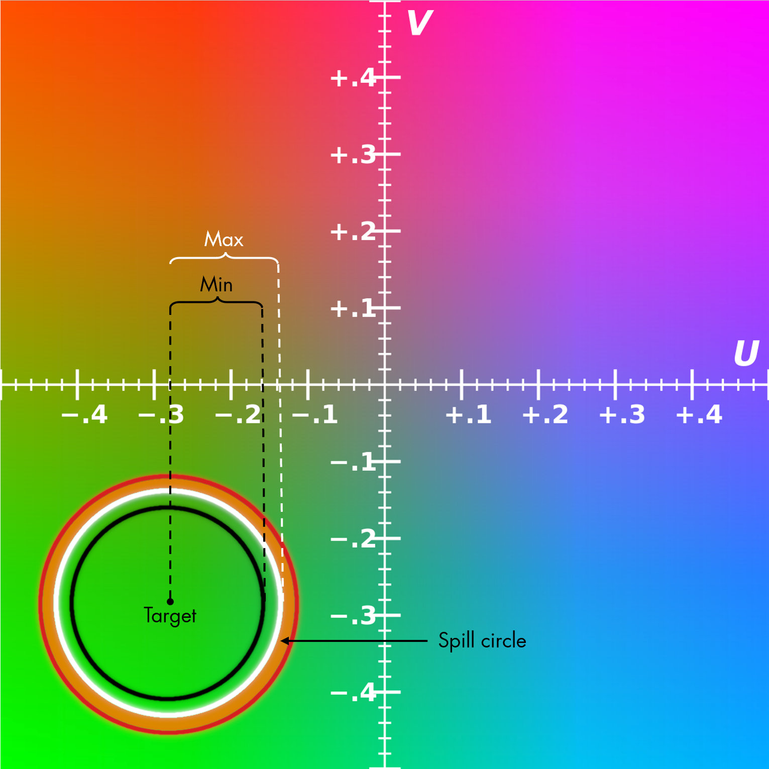
Example U-V color plane with Y = 0.5. Representation within sRGB color gamut (modified)
You can read more about this effect here.
KEY & FILL
The Key & Fill section allows you to make use of keying layers which you can read more about here.
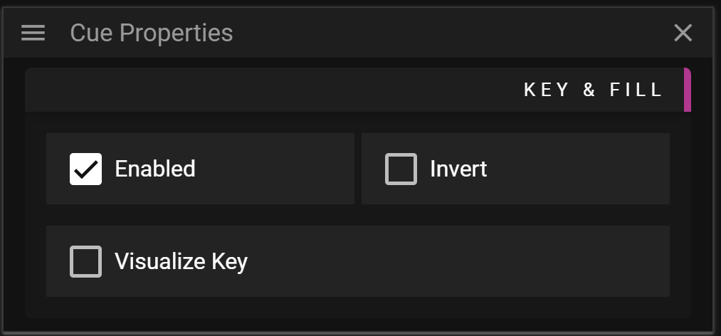
- Enabled toggles the key and fill feature on or off for this specific cue.
- If turned on it means that the pixels of this cue will be used to fill whatever pixels that all keying layers have filtered/marked.
- Invert can be activated to fill the inverted area filtered/marked by all keying layers.
- Visualize Key toggles visualization of the key on and off.
- Can be useful to understand what the key looks like for complex scenarios.
You can read more about this effect here.
MARKER
The Marker section allows you to edit data related to marker cues.
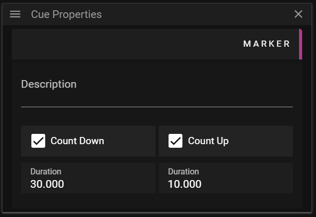
- Description contains an optional user-defined text.
- Count Down activates a countdown label on the Timeline cue object.
- Count Up activates a countup label on the Timeline cue object.
- Duration is used to control the time period in which the countdown/countup label is visible.
OUTPUT
The Output section allows you to edit data related to string output cues. A string output lets you send arbitrary data to a device on the network. The data is sent when the Timeline time reaches the cue Start Time.
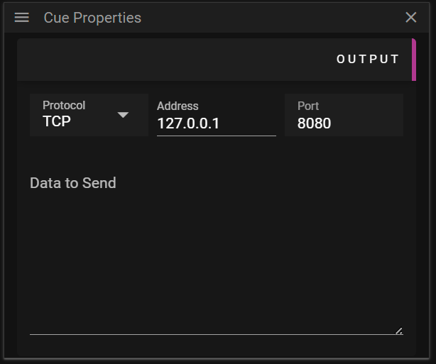
- Protocol defines the protocol to use for the data being sent.
- TCP protocol.
- UDP protocol.
- Address defines the address of the device that should receive the data.
- Data to Send defines the data, in text, that should be sent.
PLAYBACK CONTROL
The Playback Control section allows you to edit data related to control cues. A control cue can be used to edit the time and state of one or multiple Timelines.
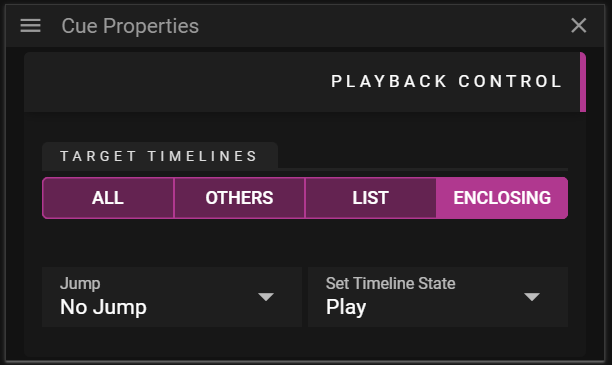
- Target Timelines defines which Timeline(s) that are affected by the Timeline Actions.
- All makes the Timeline Actions affect all Timelines.
- Others makes the Timeline Actions affect all but the Timeline in which the control cues exist.
- List makes the Timeline Actions affect all Timelines checked in the Include drop-down.
- Timeline Actions:
- Jump defines if the player should make a jump when the show reaches the cue.
- No Jump
- To Time
- To Cue
- Target Cue defines a cue Name to jump to.
- First searches for the closest cue residing after the control cue. If no match is found it then searches for cues residing before the control cue.
- Backwards to Cue defines a cue Name to jump backwards to.
- Only searches for cues residing before the control cue.
- Set Timeline State defines the state of the timeline when the show reaches the cue.
- Play
- Pause
- Stop
- Jump defines if the player should make a jump when the show reaches the cue.
CHANNEL MAPPING
The Channel section allows you to edit data related to audio cues. See Audio and channel mapping for usage
SIZE
The Size section allows you to edit data related to the size of a 3D model.
Imported 3D models are automatically scaled to fit a 1000 x 1000 x 1000 pixel cube.
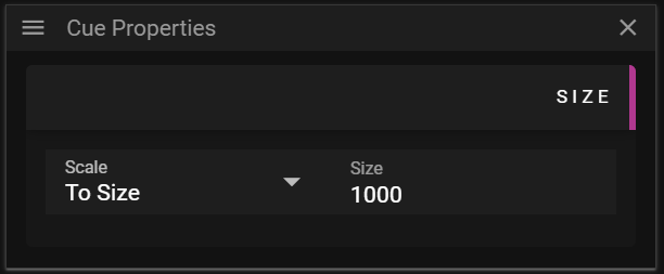
- Scale defines what method to use for setting the size.
- To Size allows you to control the maximum extent (width, height or depth) of a 3D model.
- By Factor allows you to set a uniform scale factor of the model.
- If you set this value to 1.0 you will get the original size of the 3D model.
If you want to perform non-uniform scaling you need to edit your 3D model outside Producer.
There is more information about 3D models here.
SURFACE
The Surface section allows you to edit data related to the surface of a 3D model.
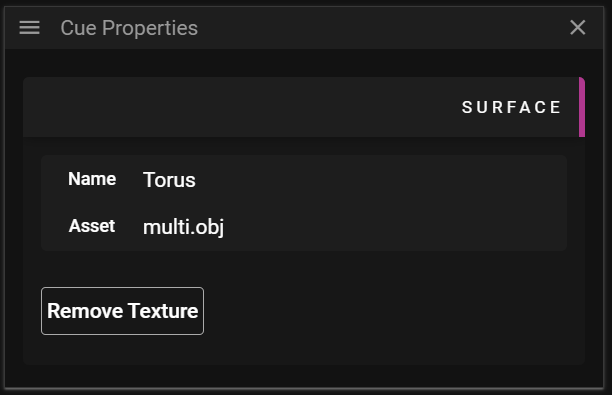
- Name shows the name of the mesh.
- Asset shows the name of the asset file that is referenced.
- Remove Texture allows you to remove media that has been applied to the mesh surface.
There is more information about 3D models here.
CONDITIONS
The Conditions section controls whether a cue is active during playback.
- Enabled - Cue plays normally.
- Disabled - Cue is skipped during playback. Disabled cues are shown with a grey striped overlay and reduced opacity on the timeline, making them easy to identify.
- Expression - Cue plays only when the expression evaluates to true. This provides powerful show control capabilities that can respond to external inputs or variable states.
For detailed information about conditional expressions, see Conditionals.
FAQ
Q. How does Looping work with In-time?
A. If you have set In-time to non-zero only the first iteration of the looping will have the initial frames trimmed (according to the In-time). Later iterations will use the full length of the asset.
Q. I have locked a cue. Can this cue be updated in any way?
A. Yes, if the cue is using a Dynamic Asset it will still be updated if an asset is updated with a new version.
CUES WINDOW
Your show at a glance. The Cues window breaks down the walls between timelines, giving you a unified view of every cue in your production. Whether you're hunting for a specific video across 50 timelines, bulk-updating media before a show, or checking that all your markers are in place—this is where you do it.
Think of it as mission control for your content.
OVERVIEW
Open the Cues window from Windows → Cues in the Producer menu.
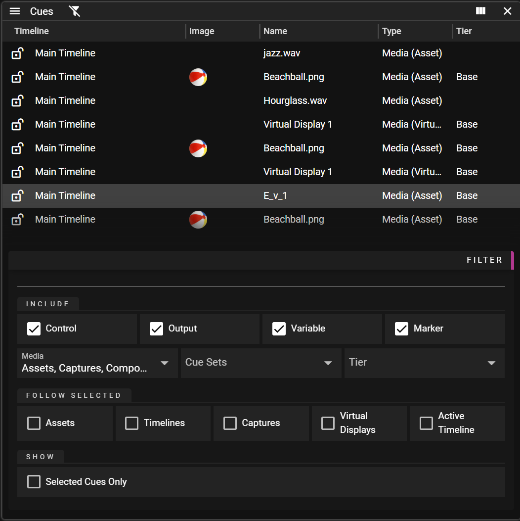
The window displays all cues from every timeline and composition in a single, searchable list. By default, you see everything—but the real power lies in the filter panel, which lets you slice and dice your cues in countless ways.
QUICK NAVIGATION:
- Double-Click any cue → Jump to it in the Timeline Editor
- Alt+Double-Click → Jump playback to that exact moment
THE FILTER: WHERE THE MAGIC HAPPENS
Click the filter icon to reveal the most useful feature of the Cues window. This is where a list of thousands of cues becomes exactly the dozen you need.
Text Search
Type to instantly filter by name. Simple but effective:
- Case-insensitive: "INTRO" finds "intro", "Intro", "INTRO"
- Multi-word AND: "dogs eating" finds cues containing BOTH words
- Partial match: "intro" finds "intro_video", "show_intro", "Introduction"
Cue Types (Include)
Show or hide entire categories of cues:
Toggle What You'll See Control Pause, goto, run command cues Output Output control cues Variable Variable manipulation cues Marker Timing markers and comments Media Sources
When showing media cues, filter by where the content comes from:
Source Content Type Asset Images, videos, audio files Virtual Display Virtual display captures Composition Nested composition content Capture Live NDI/capture inputs Cue Sets & Tiers
- Cue Sets: Show only cues belonging to specific groups
- Tiers: Filter by stage tier assignment
Selection Scope: The Magic Filter
This is where it gets interesting. Make the cue list react to your selections elsewhere in Producer:
Enable This And the List Shows Asset Only cues using your selected assets Timeline Only cues from your selected timelines Capture Only cues using your selected capture inputs Virtual Display Only cues using your selected virtual displays Active Timeline Only cues from whichever timeline you're editing Example workflow: Select an asset in the Asset Manager, enable "Asset" in Selection Scope, and instantly see every cue in your show that uses that asset. Now select them all and drag a replacement asset. Done—across all timelines.
Note: Enable multiple options for AND logic. A cue must match ALL enabled criteria.
Show Selected Cues Only
A quick way to review just the cues you've manually selected. Use this when working with asset replacement, for extra security.
WORKING WITH CUES
Selection
Action Result Click Select one cue Ctrl+Click Add/remove from selection Shift+Click Select a range Ctrl+A Select ALL visible (filtered) cues Navigation
Action Result Double-Click Open cue in Timeline Editor Alt+Double-Click Jump playback to cue position ↑ / ↓ Move through cues Home / End Jump to first/last cue Drag & Drop
- From Asset Manager → Cue: Replace the cue's media
- From Asset Manager → Multiple selected cues: Replace ALL their media at once
- Drag cues out: Use in other windows
Locking Cues
The lock icon on each row tells you the cue's status:
Icon Meaning Click Action 🔓 Unlocked Lock the cue 🔒 Locked Unlock the cue 🔒 (dimmed) Timeline is locked Can't modify—unlock timeline first With multiple cues selected, clicking any lock icon affects them all.
REAL-WORLD SCENARIOS
Here's where the Cues window really shines—tasks that would take hours become minutes.
🔄 BULK MEDIA REPLACEMENT
The scenario: Client sends updated videos. You need to replace "intro_v2.mp4" with "intro_v3.mp4" across 30 timelines.
The solution:
- Search for "intro_v2" in the filter
- Ctrl+A to select all matching cues
- Drag "intro_v3.mp4" from Asset Manager onto any selected cue
- Done. All 30 cues updated.
🔍 FIND EVERYTHING USING AN ASSET
The scenario: You need to know everywhere a specific video is used before deleting it.
The solution:
- Select the asset in Asset Manager
- Enable "Asset" in Selection Scope
- Instantly see every cue using that asset, across all timelines
✅ PRE-SHOW CHECKLIST
The scenario: 30 minutes to showtime. You need to verify the show is ready.
Quick checks:
- Filter to Markers only → Verify all timing cues are named properly
- Sort by Timeline → Scan for any locked cues that shouldn't be
- Enable Active Timeline in Selection Scope → Review each timeline's cues quickly
📋 MARKER AUDIT
The scenario: Creating a run sheet. You need all markers with their times.
The solution:
- Disable all cue types except Marker
- Enable the Start column
- Sort by Start for chronological order, or Timeline for per-timeline grouping
- Copy the data for your documentation
🎯 FOCUSED EDITING WITH SELECTION SCOPE
The scenario: You're editing Timeline A and only want to see its cues.
The solution:
- Enable "Active Timeline" in Selection Scope
- Save this as a preset called "Current Timeline Only"
- Now the cue list automatically follows wherever you're working
🎨 CUE SET MANAGEMENT
The scenario: Managing alternative content versions for different venues.
The solution:
- Filter by specific Cue Set
- Enable the Cue Set column to see group assignments and active variants
- Make bulk changes to all cues in that group
COLUMNS
Customize your view with these columns (drag to reorder, use ⋮ menu to show/hide):
Column What It Shows Visible by Default Timeline Source timeline/composition + lock status ✓ Thumbnail Visual preview of media cues ✓ Name Cue name (auto-generated from content) ✓ Type Kind + source, e.g., "Media (Asset)" ✓ Tier Stage tier assignment Start Position in timeline ✓ Duration Cue length Countdown Live countdown to markers during playback ✓ Cue Set Group name + active variant Tip: Click any column header to sort. Click again to reverse.
FILTER PRESETS
Once you've built filters you use frequently, save them as presets for instant access.
- Dropdown: Load a saved preset
- 🗑️ Delete: Remove the preset
- ↺ Restore: Undo your changes, reload the preset
- 💾 Save: Update the current preset (or ➕ to create new)
POWER USER TIPS
💡 Create task-specific presets: "All Markers", "Video Content", "Active Timeline Only", "Capture Sources"—switch contexts instantly.
💡 Use the Countdown column during live shows: See time remaining to each marker without leaving your cue overview.
💡 Combine filters for precision: Selection Scope + Text Search + Cue Type = surgical precision in huge shows.
💡 Watch for blind edit highlights: Cues from blind-edited timelines have a distinct background color and 👁️ icon—you're editing without seeing the result.
💡 Ctrl+A is context-aware: It selects all visible cues, so filter first, then select all. Perfect for bulk operations.
The Cues window transforms show management from timeline-by-timeline tedium into efficient, global operations. Master the filter, and you'll wonder how you ever worked without it.
Cue Sets
Overview
Cue sets are used for changing media of one or multiple cues live. With cue sets, you can instantly switch between different content variants while maintaining consistent timing, positioning, and effects.
Tip The same can be achieved using Cue Conditions, but Cue Sets makes it much easier to organize and overview your content.
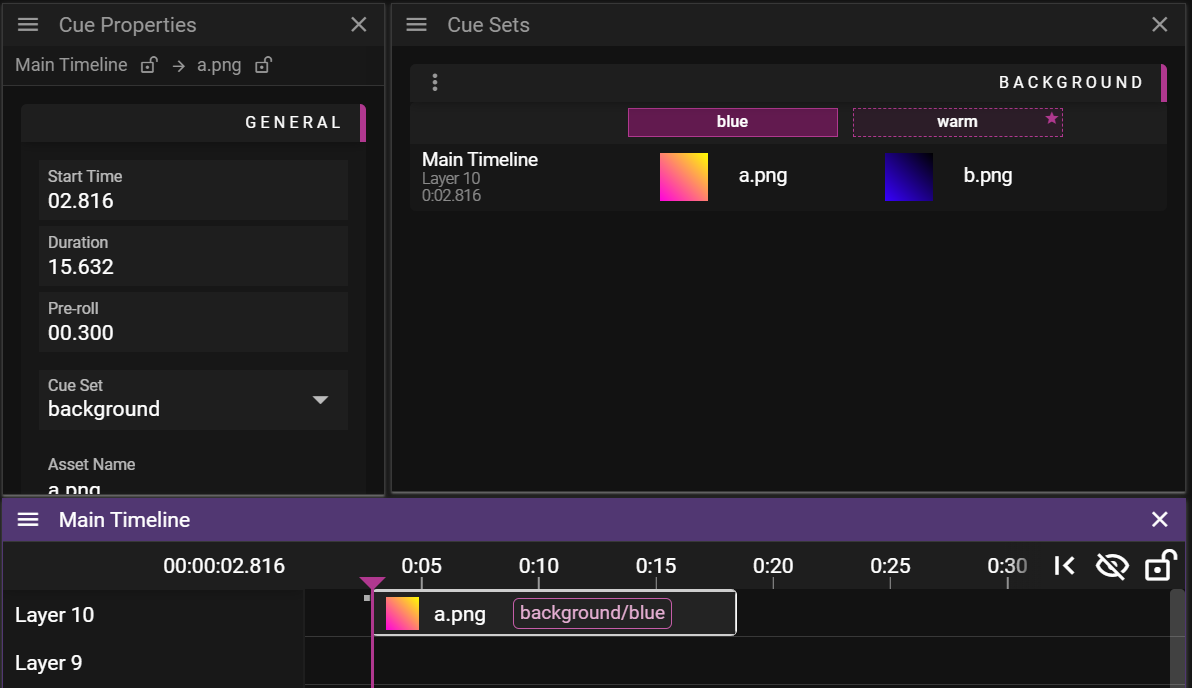
Quick start
- Create a cue set and a variant in the Cue Sets window
- Add cues by changing their Cue Set property. Multi-select works
Key Concepts
Cue Sets
A Cue Set is a collection of media cues that are linked together. Each Cue Set can have multiple Variants, which are different versions of the media content that appear at the same positions and timings in your timelines.
Variants
Variants are alternative versions of media content within a Cue Set. For example, you might have a "Rehearsal" variant with placeholder graphics and a "Show" variant with final content. Switching between variants affects all cues in the group simultaneously.
Creating a Cue Set
- Click the New Cue Set option from the window menu
- Enter a name for the group (e.g., "Opening Graphics")
- Enter a name for the initial variant (e.g., "Rehearsal")
- Click Create
Adding Cues to a Group
Cues are added to groups from the Cue Property Window. Cue Property Window has a dropdown for Cue Set.
Creating Variants
To create alternative versions of your media:
- Right-click on a group header
- Select New Cue Set Variant
- Enter a name for the variant (e.g., "Final Show")
- Choose whether to duplicate content from an existing variant
- Click Create
Managing Variants
Each variant has several management options:
- Duplicate: Create a copy of the variant with all its media
- Rename: Change the variant's name
- Set Default: Mark this variant as the default when the show loads
- Delete: Remove the variant (not available for active or default variants)
Activating Variants
To switch to a different variant:
- Click on the variant name in the column header or use external protocol
- The active variant will be highlighted
- All media cues in the group will instantly update to use the new variant's content
Cue Sets Window
Cue Information
Each row shows details about where the cue appears:
- Timeline Name: The name of the timeline containing the cue
- Layer Number: The layer position (counting from 1)
- Time Position: The timecode where the cue starts
Media Information
Each cell in the table shows:
- Thumbnail: Visual preview of the media content
- Filename: Name of the asset being used
- Hover Tooltip: Full asset name if truncated in the display
Variant Status Indicators
- Solid Border: Currently active variant
- Star Icon: Default variant (used when the show loads)
- Dashed Border: Inactive variant
Navigation Features
Clicking on any cue row will:
- Activate the appropriate timeline window
- Scroll to the cue's position
- Select the cue in the timeline
This makes it easy to locate and modify cues that are part of a group.
Usage Examples
Event with Multiple Themes
- Create a Cue Set for each section of your event (Opening, Transitions, Backgrounds)
- Create variants for each visual theme (e.g., "Cosmic", "Underwater", "Digital")
- Design cohesive visual elements for each thematic world
- Transform your entire environment instantly by switching themes mid-show
Season-Specific Content
- Create Cue Sets for your venue's permanent installation
- Create variants for different seasons (e.g., "Spring", "Summer", "Winter", "Holidays")
- Pre-program all seasonal content with appropriate imagery and colors
- Schedule automated theme changes based on calendar dates
Language Localization
- Create Cue Sets for text-based content
- Create variants for each language (e.g., "English", "Spanish", "French")
- Switch languages by activating the appropriate variant
Rehearsal to Production
- Create variants labeled "Rehearsal" and "Show"
- Use placeholder content in the rehearsal variant
- Add final approved content to the show variant
- Switch to final content with one click when ready
Best Practices
- Logical Grouping: Create Cue Sets for content that logically belongs together
- Consistent Naming: Use clear naming conventions for both groups and variants
- Default Settings: Always set an appropriate default variant
- Preparation Variants: Create separate variants for rehearsals and testing
NOTE: Cue properties are shared between all variants. This may lead to issues if content has different size, different length ...
The Cue Sets Window provides a powerful tool for managing multiple versions of content in your production, allowing for quick and efficient content switching without changing cue timing or positioning.
Conditional Render / Conditional Trigger
Conditional Rendering and Conditional Triggers are important features in WATCHOUT. They provide a powerful section in the cue properties to turn on and off rendering or prevent a control cue from executing. This functionality can be controlled through expressions, allowing integration with external inputs or variable cues.
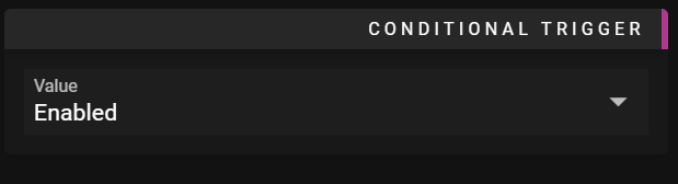
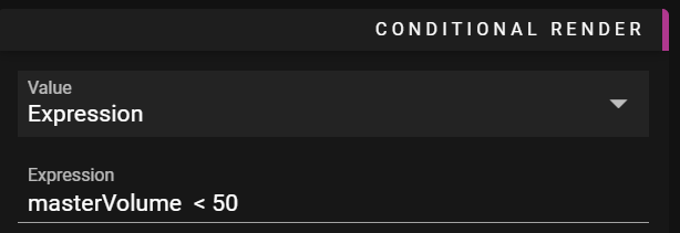
Use Cases
Skip a control cue after walk-in loop
When you need to bypass specific control cues based on show conditions.
Render only one of several possible cues
By placing cues on multiple layers and setting conditions to show only the desired one.
Tip see Sets for another way to conditionally render media.
EFFECTS
In WATCHOUT, Effects (called tweens in previous WATCHOUT versions) are applied to media Cues. An Effect is a real-time change to a media Cue when it is played back.
EFFECT MENU
Effects can be toggled on a media Cue by selecting it in the Timeline and using the Effect menu, or right clicking the Cue, and accessing the Effect menu that way.
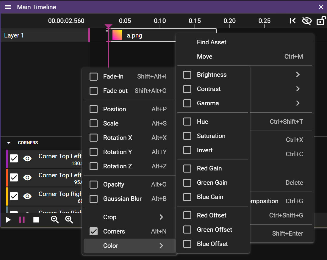
EFFECT VIEW
Effects are shown in a single unified view. To the left there is a collapsible list of the Cue's Effects. To the right is the keyframes/tween points and their curves.
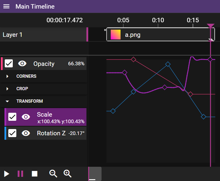
Left View
This effect list contains:
- The color of the effect
- A checkbox if the effect is enabled/disabled in rendering
- An eye icon to mute this effect in the right view
- Effect name and value
Tip 1: You can change what color a tween has in Edit Menu/Tween Colors
Tip 2: You can "solo" a tween by shift-clicking the eye icon
Right View
Here you add and move key points. Multi-select works to move many points at once.
Tip: You can move key points to the same time by multi-selecting and changing their time property.
Read more about Tween Points here
You can also edit the tween points in their property window.
In the Properties window for Effects you can generally edit the Expression for this Effect. Normally the expression is only tweenValue, but this may be changed to any expression you want.
Additional Resources
Advanced Control: Learn how to drive effects with Expressions and Variables
Effect Reference: View the complete list of all Tweenable Effects
TWEEN POINTS
As previously mentioned, Tween Points can be found in the Effect curve view. You can edit them by
- clicking on a curve to add a point.
- clicking a point to select it, and move it by dragging.
- clicking anywhere else and drag to form a selection rectangle.
TWEEN POINT PROPERTIES
In the Properties window for Tween Points you can edit the time from start of the Cue, the value of the point, and what Transition to use when transitioning to this point, from the one before.
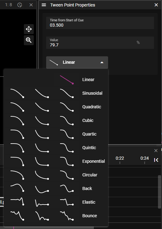
TRANSITIONS
As seen in the last image, there are a few Transitions to choose from. Linear is the default one, then there are some with different kind of smoothness, from Sinusoidal to Circular. Back, Elastic and Bounce add a special twirl to the Effect curve.
Corners & Crop UI
Both Corner and Crop effects can be manipulated directly in the Stage view for intuitive visual editing.
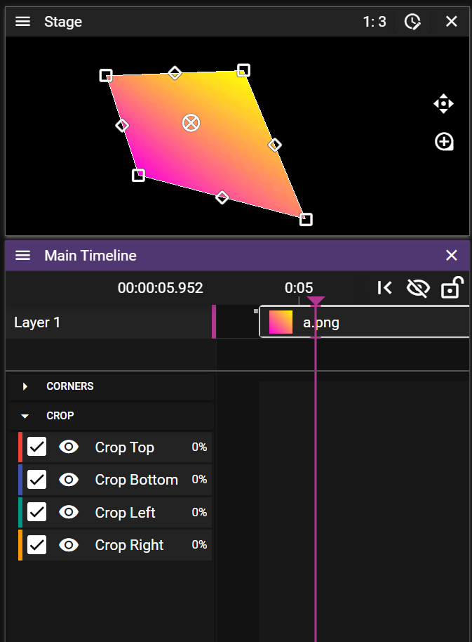
Corner Controls
The four corner points (shown as rectangles at the corners) allow you to:
- Adjust perspective and distortion
- Map content to irregular surfaces
- Create skewed presentations
- Simulate 3D perspectives without full 3D transformation
Simply drag any corner point to the desired position. The media will distort accordingly.
Crop Controls
The four mid-side controls (shown as rotated rectangles) allow you to:
- Trim unwanted portions of media
- Create reveal effects
- Design custom framing
- Build split-screen presentations
Drag any crop handle inward to remove that portion of the media from view.
For more detailed information on creating animations with these effects, see All Tweenable Effects.
POSITION EFFECT
The Position Effect is quite different compared to other effects. Like other effects you can see the tween points in the Effect curve view. But the value of the tween points can not be changed by dragging the tween point up/down in this view. That is because the value of this Effect is the position of the Cue on Stage, which consists of three values: X, Y and Z. Thus, the Position Tween Points can also be viewed, selected and dragged in the Stage window.
Start creating an animated Position Effect like this:
- Select a media Cue.
- Activate the Position Effect in the Effects menu, or by right clicking the Cue and locate the Position Effect that way.
- Move the Timeline marker forward a bit, eg towerds the end of the Cue.
- Click and drag the Cue in the Stage window, to a new position
It should look something like this:
Move the Timeline marker between the two points, and you can see that the position of the Cue on Stage is animated between these two positions. You can keep adding more points by placing the Timeline marker and moving the Cue on Stage. You can also, as with other Effect curves, click on the curve in the curve view, to add more points.
VISUALIZES MOVEMENT SPEED
The Position Effect curve does not represent the value of the Position Effect, but the progress along the Position Effect curve. This is why the first point is allways at the bottom of the curve view, as this is the beginning of the curve, and the last point is at the top, corresponding of the end of the curve. To demonstrate how this can be helpful, here is an example:
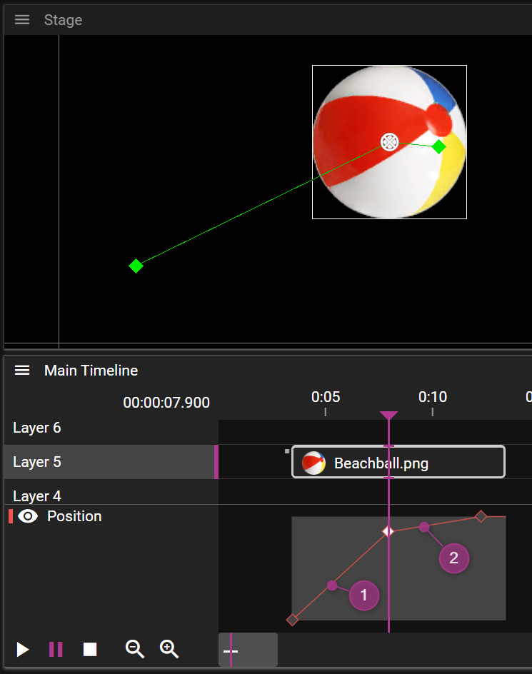
As you can see, the two last points are placed close to each other on the Stage, but on the Timeline, in the Effect curve view, you can see that they are spaced further apart. This means that the movement speed will differ when playing back this animation, it will slow down when moving past the second point. You can see this in the Effect curve, by looking at the incline of the curve: higher incline means higher speed (1), and lower incline means lower speed (2).
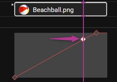
By moving the middle point to the left on the Timeline, until the incline of the segment before and after the point are equal, you get movement with the same speed across the animation.
POSITION EFFECT PROPERTIES
Here you can, besides setting the expressions to control the three values of this Effect (X, Y and Z), set the ORIENT CUE ALONG PATH property of the Effect. Setting this property will make the Cue rotate, to orient itself along the direction of the movement curve. It may look something like this:
POSITION TWEEN POINTS
Position Tween Points are visible as green diamonds in the Stage window, when the cue they belong to is selected. Here they can be selected, dragged around, and deleted. In the Effect curve view, only their time value can be dragged, as mentioned before. If you switch the Stage to the First Person mode, you can move the points in all directions using the axis gizmo.
POSITION TWEEN POINT PROPERTIES
Besides the position value of the tween point, you can edit the following:
SMOOTH HANDLES
Set the Smooth In and/or Smooth Out properties to get handles to control the direction of the position curve. Use these to generate non-linear curves between the position points on Stage, to get a "smooth" movement animation. The control handles are visible as yellow diamonds in the Stage window. They can be linked or unlinked, using the Linked Handles property. See this example: (1): Linked handles; (2): Unlinked handles.
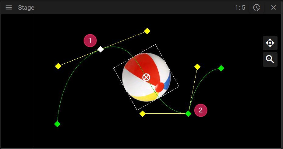
Use linked smooth handles together with the speed visualization, to get a guaranteed smooth movement animation.
TRANSITION
Use Transitions to control the speed of movement across the position curve. For example they can be used to stop the animation smoothly on a point, and then smoothly accelerate up to speed again.
CHROMA KEY
Chroma keying is an effect you can apply to a visual cue to filter out all pixels of a specific chroma. A common case for this is to hide the background of a video, by recording the video in front of a green/blue screen and then applying a chroma key effect to hide the background. Once the background is hidden you are free to replace it with something completely different.
If you are familiar with alpha masking you can think of chroma keying as a way to define a dynamic alpha mask.
You can read more about how you can activate and adjust this effect in the Cue Properties.
Below is a simple example where we filter out a hand against green background:

This is what the end result looks like:

This is what it looks like if Show Alpha Mask is enabled in the cue properties (notice the red pixels around the outline of the hand):

For more information about Chroma key, refer to Wikipedia
KEY & FILL
The Key & Fill effect can be useful for scenarios where you want to either highlight or hide specific pixel areas of one or multiple cues. It can also be useful in scenarios where you want to do creative fading effects.
As the name suggests it consists of two pieces:
- Key where you specify one or multiple pixel areas.
- Fill where you specify what content you want to use to fill the Key pixel areas.
The Key is created by first changing one or multiple layers into Keying Layers. The pixels for all cues placed on a Keying Layer are combined into a single Key. Then all keys, regardless of which Timeline the key belongs to, are further combined into a unified Key. The pixel areas defined by this Key can then be referred to by cues that want to Fill the Key with content.
You can read more details about Keying Layers and how to define them here, and you can read more about how to define Fill here.
The example below shows how to define a simple Key & Fill effect:
- Add a cue that you want to use for Key.
- Click on the cue's layer and in Layer Properties select to use Alpha Key to define the Key pixel areas.
- In Layer Properties turn it into a Keying Layer with the Enabled checkbox.
- Add a cue you want to use for Fill.
- Select the cue and in the Key & Fill section of the Cue Properties toggle the Enabled checkbox on.
- Note: The paint bucket symbol in the cue indicates the Key & Fill effect.
ALL TWEENABLE EFFECTS
Understanding Effects in WATCHOUT 7
WATCHOUT 7's effect system provides tools to transform and animate your media. Using the tween editor, you can create sophisticated effects that bring your presentations to life with professional-quality animations, transitions, and visual enhancements.
Getting Started with Effects
Accessing Effects
- Select a cue in the timeline editor
- Open the tween editor at the bottom of the timeline window
- Add keyframes by clicking in the tween editor
Basic Animation Workflow
- Choose a property to animate (Position, Scale, Opacity, etc.)
- Set keyframes at different points in time
- Adjust property values at each keyframe
- Choose interpolation method (Linear, Ease In/Out, Bezier)
- Preview the animation using the timeline playback controls
Position and Transformation Effects
Position Effects
Usage: Create entrance/exit animations, motion paths, or dynamic layouts
- Create flying elements by animating objects across the screen
- Simulate camera movements by moving background content
- Create parallax effects by moving layers at different speeds
- Build reveal animations by combining with other effects
Scale Effects
Usage: Emphasize content, create dynamic sizing, or simulate 3D perspective
- Draw attention to content by growing it at key moments
- Create pulse effects with repeated scale animations
- Simulate approaching/receding objects with coordinated scale changes
- Create "Ken Burns" effects on still images by combining with position tweens
Rotation Effects
Usage: Create spinning elements, dynamic transitions, or orientation changes
- Build spinning text intros by animating Z-rotation
- Create page-turn effects with Y-axis rotation
- Design 3D-like transitions by combining X and Y rotations
- Add subtle movement to static elements with gentle rotation animation
Corners Effects
Usage: Create perspective distortions, surface mapping, or custom shapes
- Map content precisely onto perspective surfaces
- Create page-curl effects by manipulating individual corners
- Design dynamic transitions by animating corner positions
- Simulate 3D space without full 3D transformation
Visual Effects
Opacity Effects
Usage: Create fades, transparency effects, or layered compositing
- Design fade in/out transitions at the beginning/end of content
- Create ghost-like overlays with partial transparency
- Build cross-dissolves between different media elements
- Add subtle visual hierarchy through varied opacity levels
Blur Effects
Usage: Create focus effects, stylistic blurs, or dreamy transitions
- Draw attention by blurring background elements
- Create depth-of-field effects by selectively blurring content
- Design dream sequences or flashbacks with animated blur
- Build focus transitions by animating blur levels
Crop Effects
Usage: Create reveal effects, masking, or dynamic framing
- Design wipe transitions by animating crop edges
- Create split-screen effects with precisely cropped content
- Build peekaboo animations that gradually reveal content
- Design picture-in-picture effects with cropped content
Color Effects
Brightness Effects
Usage: Create lighting changes, highlights, or mood transitions
- Simulate day-to-night transitions with brightness animation
- Create flash effects with quick brightness pulses
- Design spotlight effects by combining with other properties
- Enhance the visual hierarchy by highlighting important elements
Contrast Effects
Usage: Enhance visibility, create mood, or stylistic effects
- Improve readability of text against changing backgrounds
- Create dramatic moments with increased contrast
- Design flashback sequences with period-appropriate contrast
- Build mood transitions through subtle contrast changes
Gamma Effects
Usage: Adjust midtone brightness while preserving highlights and shadows
- Fine-tune the appearance of footage with exposure challenges
- Create smooth transitions between lighting conditions
- Correct underexposed or overexposed content
- Design stylistic effects that maintain detail in highlights and shadows
Hue Effects
Usage: Create color shifts, mood changes, or psychedelic effects
- Design color cycling effects for dynamic backgrounds
- Create mood transitions through subtle hue shifts
- Build stylized looks by shifting specific color ranges
- Create "through the decades" effects with period-appropriate color grading
Saturation Effects
Usage: Control color intensity for mood or emphasis
- Design transitions from color to black and white
- Create emphasis by saturating important elements
- Build nostalgic looks with reduced saturation
- Design psychedelic effects with hyper-saturation
Invert Effects
Usage: Create negative image effects or dramatic transitions
- Design X-ray-like visual effects with full inversion
- Create dramatic transitions with animated invert values
- Build horror or thriller effects with momentary inversions
- Design artistic effects with selective inversion
Channel-Specific Color Effects
RGB Offset Effects
Usage: Fine-tune color balance or create color cast effects
- Correct color temperature issues in footage
- Create day-for-night effects by adjusting RGB balance
- Design period-appropriate color looks (sepia, technicolor, etc.)
- Build mood-enhancing color grading
RGB Gain Effects
Usage: Control color channel intensity for dramatic color effects
- Create high-contrast stylized looks
- Design color temperature shifts for time-of-day changes
- Build dramatic mood lighting effects
- Create unique artistic color grading
Audio Effects
Volume Effects
Usage: Create fades, dynamic volume changes, or emphasis
- Design smooth audio fades at content boundaries
- Create ducking effects when voice-over begins
- Build tension with gradual volume increases
- Design environmental transitions with coordinated audio changes
Creative Applications
Entrance and Exit Effects
Combine Position, Scale, Opacity, and Rotation to create:
- Flying entrances from off-screen
- Dramatic scale-up reveals from center
- Spinning introductions with fade-in
- Graceful exits that maintain viewer attention
Transitions Between Content
Coordinate multiple effects to create:
- Smooth cross-dissolves between scenes
- Dynamic wipe transitions with animated crop edges
- Page-turn effects using rotation and corner manipulation
- Push/pull transitions with coordinated position animation
Emphasis Effects
Use timed effects to draw attention:
- Momentary brightness/contrast increases
- Gentle scale pulsing of important elements
- Brief saturation boosts for key information
- Focus effects with selective blurring of surrounding elements
Environmental and Mood Changes
Animate multiple properties to transition between environments:
- Day-to-night transitions with coordinated brightness, contrast, and hue
- Weather changes using brightness, contrast, and blur
- Time period shifts with appropriate color grading
- Mood transitions through subtle color and brightness adjustments
Advanced Techniques
Multi-Property Animation
Animate multiple properties simultaneously for sophisticated effects:
- Coordinate scale, position, and rotation for complex 3D-like movement
- Combine color effects for comprehensive atmosphere changes
- Link opacity with blur for ethereal transition effects
Curve Editing
Shape the pace and feel of animations:
- Use ease-in/out curves for natural movement
- Apply linear curves for mechanical or technical effects
- Create custom bezier curves for precise motion control
By mastering WATCHOUT 7's effect system, you can create professional-quality animations that enhance your presentations and create memorable visual experiences for your audience.
DEVICES WINDOW
Introduction
The Devices Window in WATCHOUT provides a complete overview of all output, capture, and audio devices across your production environment. This interface allows you to manage displays, projectors, virtual outputs, capture sources, and audio devices from a centralized location.
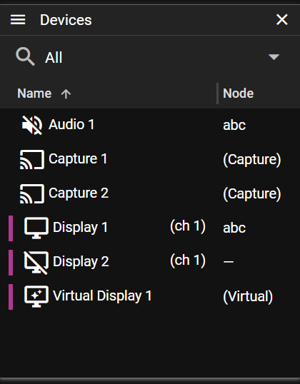
Managing Devices
Filtering and Sorting Devices
Use the filter dropdown at the top of the window to quickly find specific device types. You can also use the search icon (🔍) to filter devices by name or other properties.
Sort the list by hovering over any column header until sorting arrows appear, then click the arrows to sort.
Adding Devices
Use the hamburger menu in the top-right corner, or right-click in the device list to access the context menu and add:
- Add Display: Configure a new physical display output
- Add Virtual Display: Create a new virtual display
- Add 3D Projector: Configure a 3D projector output
- Add Audio Device: Set up a new audio device
- Add Capture: Create a video capture source
Editing Devices
- Double-click any device to open its properties panel
- Right-click to access context menu options
- Select multiple devices by using Ctrl+click or Shift+click
When you select a device, the Device Properties panel will display information and editing options specific to that device type. You can select multiple devices simultaneously to edit common properties across several devices at once.
Right-click on a display to access specific display functions:
- Edit Warp: Open the warp editor for geometric correction
- Edit Mask: Create and edit display masks
- Enable/Disable: Toggle device activation state
Right-click on an audio device to:
- Enable/Disable: Toggle device activation state
Important: Capture devices and virtual displays have special functionality - you can drag them directly to a timeline layer.
Device Types
WATCHOUT supports the following device types:
- Display
Configures how cues are recorded and presented in a show. - Capture
Configures how video and audio streams can be captured and rendered using a capture cue. - Audio
Configures the playback of audio in a show.
Best Practices
- Organize by Color: Assign consistent colors to displays for easy identification
- Group by Function: Name devices according to their purpose (e.g., "Stage Left", "FOH")
- Regular Cleanup: Remove unused devices to keep your configuration clean
- Consistent Naming: Use a clear naming convention across your production
The Devices Window is your central hub for managing all input and output devices in your WATCHOUT 7 system, providing efficient control over your entire production workflow.
Nodes
The Node Window provides a centralized interface for monitoring and controlling all nodes/ all networked devices in your WATCHOUT 7 system. This powerful tool helps you manage your entire show network from a single interface.
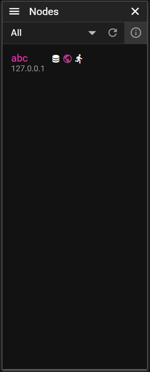
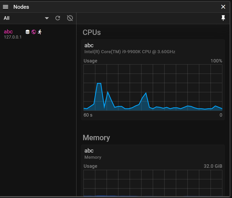
Two view options: Compact (left) and Expanded (right). Toggle with the info icon or by dragging.
- Left part is the Node List
- Right part is System Dashboard (if nothing is selected)
- Right part shows Node Info (if a node is selected)
Node List
Introduction
The Node List displays all devices in your WATCHOUT 7 network. This panel allows you to monitor device status, identify service configurations, and select devices for detailed management.
Located on the left side of the Node Management Window, the Node List serves as your command center for network supervision, giving you immediate visibility into the health and configuration of every device in your show.
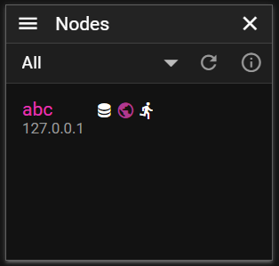
Tool Row
Filtering Options
Use the dropdown filter at the top of the node list to streamline your view:
- All Devices - Shows every detected device on your network
- Active in Show - Displays only devices actively participating in the current show
- Referred by Show - Shows devices referenced in your show configuration
Check network connectivity
Click the refresh button (🔄) to scan your network:
- Devices reachable will light up green for a while
Device Information
Each device entry in the list presents essential information at a glance:
- Host Name - The device's network name
- IP Address - The device's network address
- Service Icons - Visual indicators showing active services:
- Director (show control service)
- Runner (display output service)
- Asset Manager (media management service)
- MIDI Bridge (MIDI connectivity service)
- LTC Bridge (timecode service)
- Asset Watcher (media monitoring service)
Status Indicators
The Node List uses visual cues to communicate device status:
- Bright text - Device is in your show, online and responsive
- Red marker - Device failed to report within 5 seconds (network issue or unresponsive service)
- Faded text - Device is not in show
- Purple text - Your local device
- Progress bar - Download progress during updates
- ⚠️ icon - Version mismatch or multi-show conflict
Nodes marked with a red marker automatically return to normal once they resume reporting.
Selection Controls
Efficiently manage device selection with these controls:
- Single click - Select a single device
- Ctrl+click - Add or remove a device from selection
- Shift+click - Select a range of devices
- Ctrl+A - Select all devices
- Click empty area - Clear selection
Context Menu
Right-click on a device to access the context menu with the following options:
Display Management
- Add Display - Add a display output to the selected device
- Add 3D Projector - Configure a 3D projector on the selected device
- Add Audio Device - Add an audio output device
- Add Capture - Create a new capture source
Director Management
- Use Director - Set this device as the show director
- Clear Show from Director - Remove show from the director
- Director Settings - Configure director behavior
Asset Management
- Use Asset Manager - Set this device as the asset manager
- Close Asset Manager - Stop the asset manager service
- Asset Watcher - Configure automatic asset import
Runner Management
- Asset Cache - Manage the local asset cache
- Splash On/Off - Control the splash screen
System Operations
- Restart Services - Restart all 7NX services
- Rename Node - Change the device's network name
- Time Sync Settings - Configure NTP time synchronization
- Shutdown - Power off the selected device(s)
- Restart - Reboot the selected device(s)
- Working Directory - Set the working directory
- Network Interfaces - Configure network settings
- Software Update - Update to the latest software version
Best Practices
For optimal use of the Node List:
- Use appropriate filters to focus on relevant devices
- Regularly refresh the list when adding new nodes, or changing network setup
- Check status indicators to identify potential issues
- Pay attention to warning icons that highlight configuration problems
- Use multi-selection for batch operations on similar devices
By effectively using the Node List, you can maintain awareness of your entire network's status and quickly identify devices requiring attention.
Node Info
Overview
The Node Information Panel is a comprehensive dashboard for monitoring and managing individual nodes within your network. This detailed interface provides in-depth system information, performance metrics, file transfer status, and administrative controls for each connected device.
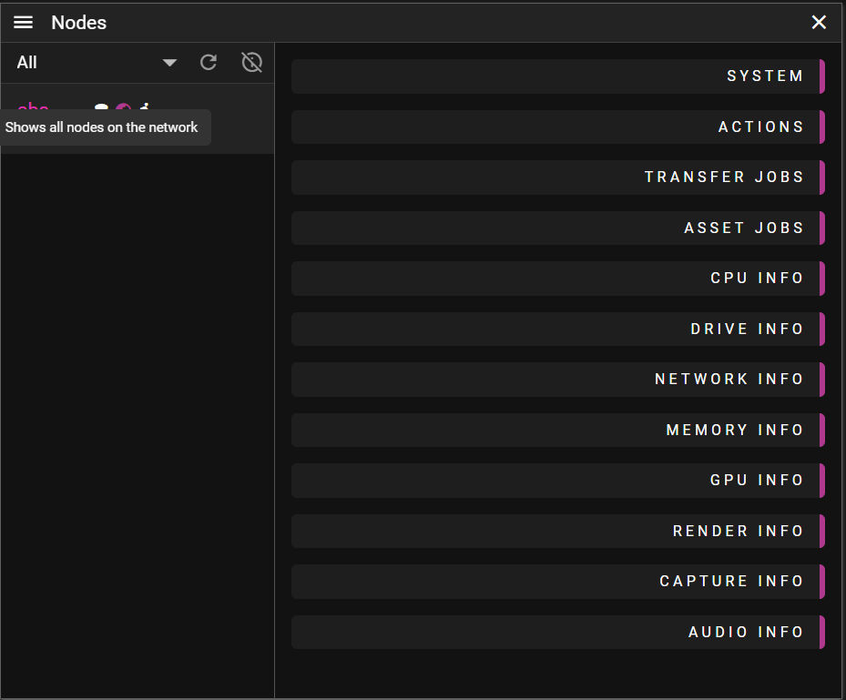
Information Categories
The Node Information Panel is organized into collapsible sections, each focused on a specific aspect of the selected node:
System
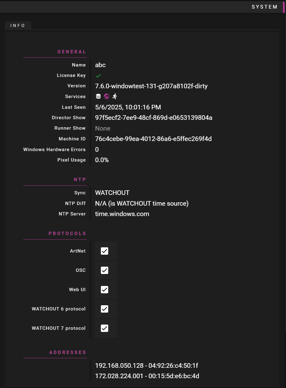
Displays essential information about the selected node. Also allow you to toggle what protocols your node responds on. Do this on the Director node, or Asset Manager node.
System Actions
Provides administrative controls for the selected node. See the Node List documentation for details.
Transfer Jobs
Displays file transfer operations in progress:
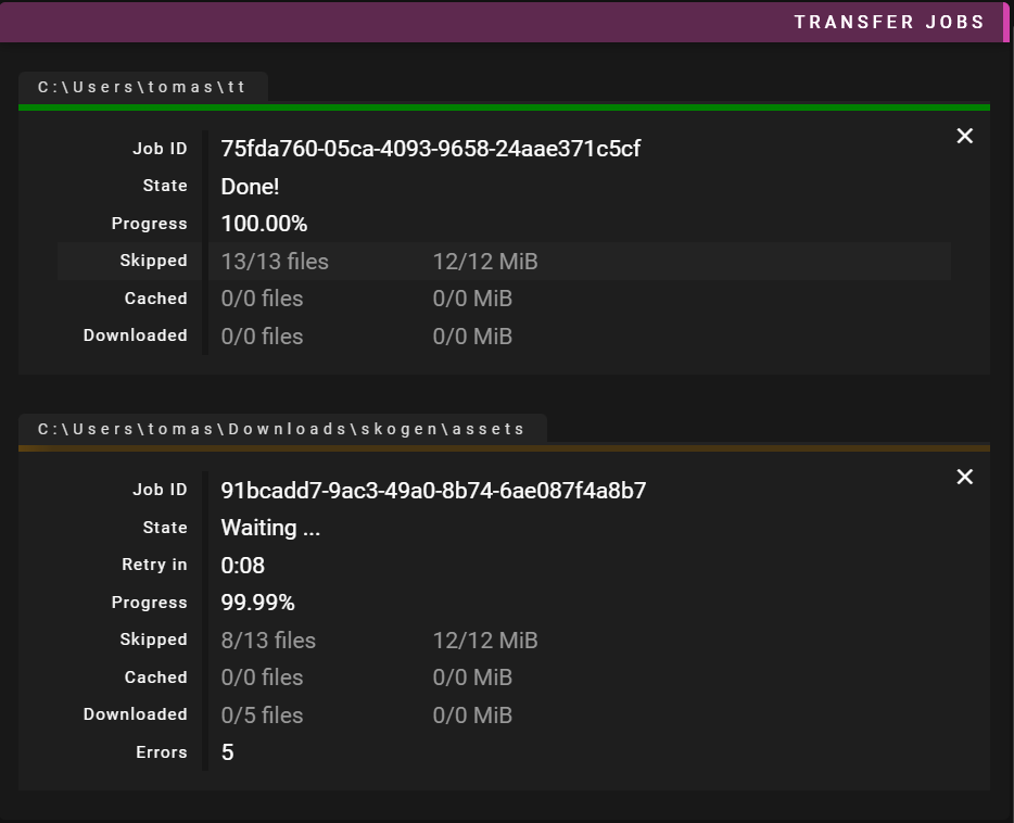
- Status Information:
- State: Current operation status (pending, working, success)
- Schedule: Time until operation begins
- Progress: Percentage complete
- Skipped Files: Files bypassed due to existing copies
- Copied Files: Local files copied
- Downloaded Files: Remote files retrieved
- Errors: Issues encountered during transfer
- Current Files: Files being processed
Hardware Monitoring
Multiple sections provide detailed hardware metrics:
-
CPU Info: Usage statistics and charts for each processor
-
Drive Info: Space usage and read/write rates with performance graphs. Note this does not currently work with raid systems.
-
Network Info: Upload and download bandwidth with traffic visualization
-
Memory Info: RAM utilization with usage trend charts
-
GPU Info: Graphics processor details with utilization graphs:
- General GPU usage
- Video encoder utilization
- Video decoder utilization
-
Render Info: Performance metrics for media playback:
- Frames per second
- Dropped media frames
- Dropped capture frames
-
Capture Info: Camera and video capture device details
-
Audio Info: VU meters for audio level monitoring
Interactive Features
Progress Tracking
File transfers and processing operations show:
- Colored progress bars indicating status
- Percentage completion indicators
- Real-time speed metrics
- Estimated time remaining
Error Handling
For operations with errors:
- Expandable error details (click arrow to expand)
- Timestamps for each error
- Descriptive error messages
- Color-coded indicators
Job Management
For active jobs:
- Cancel individual jobs with the close button (×)
- "Close All Jobs" button to cancel all operations
- Indeterminate progress for pending operations
- Color-coded status indicators
Usage Tips
- Collapsible Sections: Click section headers to expand/collapse for focused viewing
- System Actions: Use buttons in the Actions section for remote management
- Monitoring During Show Creation: Keep hardware sections open to profile performance in real-time
- Job Management: Cancel unnecessary transfers to free up bandwidth
- Error Troubleshooting: Expand error details for troubleshooting information
- Monitor capture info: Get real-time updates on capture sources used
Node Info provides comprehensive insight into a node in your network, allowing for efficient monitoring and management of all system resources from a single interface.
Dashboard
Overview
The Node Metrics Dashboard provides real-time performance monitoring for all devices in your WATCHOUT 7 network. This powerful visualization tool helps you track system resources, identify bottlenecks, and ensure optimal performance across your entire production environment.
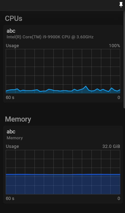
Dashboard Features
The Node Metrics Dashboard presents performance data in an intuitive grid layout with the following capabilities:
- Real-time Monitoring: View live performance metrics from all connected devices
- Customizable Layout: Pin important metrics for focused monitoring
- Detailed Charts: Analyze resource usage trends with interactive charts
- Fullscreen Mode: Maximize any chart for detailed analysis
- Category Filtering: Groups metrics by resource type
Interface Layout
The dashboard is organized into clearly defined categories:
- CPUs: Processor utilization across all cores
- Memory: RAM usage and availability
- GPUs: Graphics processing unit utilization, memory usage, and temperature
- Networks: Upload and download bandwidth consumption
- Drive Reads: Storage read operations and speeds
- Drive Writes: Storage write operations and speeds
- Render Info: Frame rates and dropped frame statistics
- Audio: VU meters for audio level monitoring
Monitoring Charts
Each metric is displayed as a card containing:
- Host Reference: The device name providing the metric
- Metric Name: The specific resource being monitored
- Chart: Real-time visualization of the metric data
- Fullscreen Button: Expands the chart for detailed analysis
Working with the Dashboard
Viewing All Metrics
By default, the dashboard displays all available metrics from all connected devices. Scroll through the categories to view different resource types.
Customizing Your View
Pinning Important Metrics
- Click the Pin icon (📌) in the top right corner to enter edit mode
- Click on any metric card to toggle pinning (pinned charts appear highlighted)
- Click the Checkmark (✓) to save your selection and exit edit mode
Only pinned charts will remain visible after exiting edit mode, allowing you to focus on your most important metrics.
Clearing Pinned Metrics
While in edit mode, click the Restore (↺) button to clear all pinned metrics and return to the default view.
Detailed Analysis
Fullscreen Mode
Click the Fullscreen (⛶) button on any chart to maximize it for detailed analysis. This view provides:
- Chart title and host reference
- Expanded visualization
- Exit button to return to the grid view
Press the Fullscreen Exit button or
Esckey to return to the dashboard.Keyboard Navigation
- Escape: Exit fullscreen mode or edit mode
- Ctrl+Click: Enter edit mode and select chart (same as using the pin icon (📌) )
- Space: Toggle pinned status while in edit mode
Using Performance Data
Resource Management
Monitor CPU, GPU, and memory usage to:
- Identify overloaded devices
- Balance workloads across your network
- Detect performance bottlenecks
GPU Monitoring (NVIDIA only)
The GPU section includes dedicated charts for:
- GPU Utilization: Processing load on the graphics card
- GPU Memory: Video RAM usage for texture and frame buffer allocation
- GPU Temperature: Thermal monitoring to prevent overheating
High GPU temperatures or memory pressure can indicate the need to optimize content or distribute load across additional devices.
Storage Performance
Track disk read/write operations to:
- Ensure media files load efficiently
- Identify slow storage devices
- Monitor available space
Network Analysis
Monitor upload/download rates to:
- Identify bandwidth constraints
- Optimize asset distribution
- Troubleshoot connection issues
Rendering Performance
Watch render metrics to:
- Ensure consistent frame rates
- Detect dropped frames
- Optimize performance-intensive content
Audio Monitoring
The Audio section provides VU meters for each device, allowing you to:
- Monitor audio levels across outputs
- Detect audio signal problems
- Balance levels between different devices
Best Practices
- Pin Critical Metrics: Focus on the metrics most relevant to your current production
- Fullscreen During Setup: Use fullscreen mode during technical setup to fine-tune performance
- Regular Monitoring: Check the dashboard periodically during shows to catch issues early
- Look for Patterns: Watch for trends that might indicate developing problems
The Node Metrics Dashboard is an important tool for maintaining performance across your WATCHOUT 7 network, ensuring smooth and reliable operation during critical productions.
CAPTURE
A capture device allows you to capture data streams produced by various sources. WATCHOUT supports capturing:
- NDI® streams over network
- Spout streams for low-latency local capture (up to 32-bit float RGBA)
- Deltacast video capture cards (including HDMI 2.1)
- MediaFoundation compatible capture devices (webcams, USB capture cards)
The captured stream can be added to a WATCHOUT show as a cue. Then you may add effects to further tweak how the captured stream is rendered.
To set up a capture stream you need to:
- Create a capture device.
- Add a stream to the device.
- Drag the device to a Timeline which will create a cue referring the captured stream.
CAPTURE PROPERTIES
In this chapter you will learn about the available Capture Properties.
GENERAL
This section contains the possibility to set a name for the capture device and define the resolution for all cues that will be referring to the captured stream.
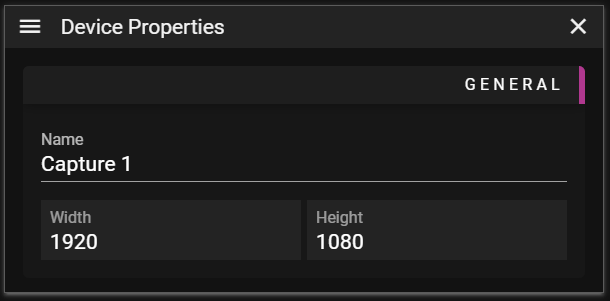
- Name - A user defined name for the capture device.
- Width - Defines the width, in pixels, of the cue associated with the stream being captured.
- Height - Defines the height, in pixels, of the cue associated with the stream being captured.
SOURCES
This section gives you the possibility to configure which streams the capture device should listen to.
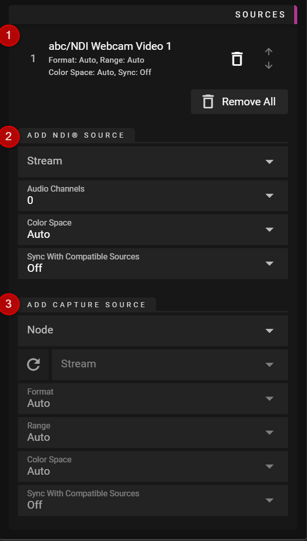
1 Sources
Shows a list of the streams that this capture device will listen to. WATCHOUT will use the first valid stream starting at the top of the list.
- Trash can button lets you remove a specific stream.
- Arrow Up/Down buttons allows you to rearrange the priority of the streams.
- Remove All - Removes all streams that have been added to the capture device.
Note: Streams are prioritized from top (highest priority) to bottom (lowest priority). If the topmost stream is unavailable, WATCHOUT will attempt to use the next available stream in the list.
2 Add NDI® Source
Captures video over network using the NDI® protocol.
- Stream - Lists all available NDI® streams. You can also manually enter a stream name if it's not discovered automatically.
- Audio Channels - Set how many audio channels you want (0 disables audio).
- Color Space - Allows you to override auto color space detection.
- Sync Mode - Controls frame synchronization behavior:
- Off - No synchronization, frames are displayed as they arrive.
- Maintain - Maintains consistent frame timing for smoother playback. Adds some latency.
TIP: If an NDI source is not automatically discovered, you can add its IP address in Show Properties > NDI Extra IPs to help WATCHOUT find it.
3 Add Capture Source
Captures video from local sources including Spout streams, Deltacast cards, webcams, and USB capture devices.
- Host - The node/machine where the capture source is available.
- Refresh - Update the stream list for this source.
- Stream - Lists all available capture streams on the selected host (Spout senders, Deltacast inputs, MediaFoundation devices).
- Format - Defines the pixel format to use for the stream, e.g., YUV, RGB (hardware capture only).
- Range - Defines the signal range to use for the stream (hardware capture only):
- Auto - WATCHOUT uses whatever range the device provides.
- Limited - WATCHOUT overrides the device setting to use limited range (16-235 for 8-bit content).
- Full - WATCHOUT overrides the device setting to use full range (0-255 for 8-bit content).
- Color Space - Override the color space interpretation:
- Auto - Automatically detect color space.
- Rec. 601, Rec. 709, Rec. 2020 - Standard broadcast color spaces.
- Rec. 2100 HLG, Rec. 2100 PQ - HDR color spaces.
- scRGB, sRGB, sRGB (gamma 2.2) - Computer graphics color spaces.
- Sync Mode - Controls frame synchronization (Off or Maintain) see NDI above.
Note: Spout capture only works when the Spout sender and WATCHOUT Runner are on the same machine. Spout provides low-latency, lossless capture supporting up to 32-bit float RGBA.
TIP: During playback you can watch the actual Capture Info in Nodes.
Supported Capture Hardware
Deltacast Video Cards
WATCHOUT supports Deltacast video capture cards including HDMI 2.1 models. These professional cards provide low-latency, high-quality capture for broadcast and live production workflows.
MediaFoundation Devices
Any capture device compatible with Windows MediaFoundation is supported, including:
- USB webcams
- USB capture cards
- Internal capture devices
Spout Sources
Spout is a real-time video sharing framework for Windows. Applications that support Spout output include:
- Resolume
- TouchDesigner
- Notch
- Unity (with Spout plugin)
- Unreal Engine (with Spout plugin)
- OBS (with Spout plugin)
Expressions and Variables
Expressions and Variables in WATCHOUT 7 provide a powerful way to create dynamic behaviors throughout your productions. These mathematical and logical formulas are the engine, with variables serving as their dynamic inputs.
Think of expressions as the recipes and variables as the ingredients that can change over time.
Expressions
Expressions can be used in various contexts throughout WATCHOUT 7 to create dynamic show control:
- Timeline control - Start, stop, and adjust timelines based on conditions
- Conditional logic - Show or hide cues
- Tween manipulation - Modify cues look and feel
For more details: Working with Expressions
Variables
WATCHOUT 7 can receive input from various external sources to control variables in your productions. These input methods allow for dynamic control and integration with other show systems.
Available Input Methods
Each of the following input method has unique advantages. You can use multiple input methods simultaneously to create flexible, responsive shows.
- MIDI and MSC - Control via music equipment and show control systems
- OSC - Modern network-based control protocol
- DMX - Lighting control protocol integration
- Variable Cues - Cue control of variables
- PSN - Posi Stage Net protocol
- External WATCHOUT Protocols - Used from Control Systems
- User Interface - Manual control via Producer slider
For more details: Variable Properties
The combination of expressions and variables creates a powerful system for building responsive, adaptable shows that go beyond linear media playback.
# Variable Inputs
There are many ways to set variable values in WATCHOUT 7. Each input method offers different capabilities for controlling your show.
Using Multiple Input Methods
You can use different input methods simultaneously, allowing for flexible show control from various sources.
Important Caution
Take care to avoid setting the same variable from multiple input methods, as this can lead to unpredictable behavior when input sources conflict.
Variable as Cue
Variable cues dynamically change the value of variables directly from your timeline. Create one by dragging a variable from the Variable window to a timeline.
This is powerful as it lets you update variable values from inside WATCHOUT 7 itself.
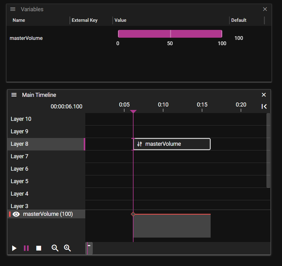
A Variable cue is the only way to change the variable value inside WATCHOUT 7. This effect changes the value either by a tween track, or by an expression containing other variable(s).
Important Behavior Notes
- Variable cues execute only when you play through them in real-time
- For guaranteed variable updates, always play from a position slightly before the cue
- Multiple variable cues can create complex control networks throughout your production
OSC Support in WATCHOUT 7
WATCHOUT 7 provides native Open Sound Control (OSC) support through the Director node, allowing control via modern show control systems, mobile devices, and custom applications.
Connection Methods
WATCHOUT Director listens for OSC commands on two ports:
- UDP: Standard OSC on port 8000
- TCP: OSC over TCP on port 8001 (using OSC TCP v1.0 protocol)
Variable Control via OSC
Any OSC message not matching the timeline control patterns can be used to control variables:
-
For each message, WATCHOUT creates input keys for each argument:
- Format:
osc.addr("ADDRESS/INDEX") - Example: For message
/fader 0.5 0.7, WATCHOUT creates:osc.addr("/fader/0")with value 0.5osc.addr("/fader/1")with value 0.7
- Format:
-
Supported value types:
- Float: Decimal values (e.g., 0.5)
- Integer: Whole numbers (automatically converted to float)
-
To use these values, create variables with matching keys:
- Variable key:
osc.addr("/fader/0") - This variable will now receive values from the first argument of
/fadermessages
- Variable key:
Timeline Control Commands
Control timelines using these address patterns:
- /wo/play/:timelineId - Start playing a timeline
- /wo/pause/:timelineId - Pause a timeline
- /wo/stop/:timelineId - Stop a timeline completely
- /wo/run/:timelineId - Reset and play a timeline
Optional Position Arguments
Timeline commands accept optional time arguments:
- Integer value (in milliseconds) to specify a time position
- Float value (in seconds) to specify a time position
Cue Points
Target specific cues within timelines:
- /wo/play/:timelineId/:timelineCueId - Play from specific cue
- /wo/pause/:timelineId/:timelineCueId - Pause at specific cue
- /wo/stop/:timelineId/:timelineCueId - Stop at specific cue
Examples
# Play timeline with ID 0 (main timeline)
/wo/play/0

# Play timeline with ID 3
/wo/play/3

# Pause timeline with ID 42
/wo/pause/42

# Stop timeline with ID 42
/wo/stop/42

# Pause timeline with ID 99 at 00:00:01.042 using Integer (milliseconds)
/wo/pause/99 1042

# Pause timeline with ID 99 at 00:00:01.042 using Float (seconds)
/wo/pause/99 1.042

# Pause Timeline 3 at Cue 12
/wo/pause/3/12
Best Practices
For optimal results with OSC control:
- Use consistent address patterns across your project
- Test all OSC functionality before live performances
- Use dedicated networks for show-critical OSC traffic
- Only use float or integer values in your messages
- Create a documentation sheet for your OSC implementation
TCP vs UDP Considerations
Both protocols work well under normal network conditions. Choose based on your show's requirements:
- UDP (port 8000) - Processes messages immediately but might occasionally drop messages during network congestion
- TCP (port 8001) - Guarantees message delivery but might significantly delay execution during network issues
For most installations, either protocol will work effectively. On challenging networks, you'll need to decide whether lost messages (UDP) or potentially delayed ones (TCP) would be less problematic for your specific application.
By effectively utilizing WATCHOUT 7's OSC capabilities, you can create dynamic, responsive productions that integrate seamlessly with modern control systems.
DMX VARIABLE
NOTE: As WATCHOUT does not directly support DMX input, you'll need to utilize an Art-Net adapter to convert DMX to Ethernet. Once converted, you can add a Variable.
You can listen to Art-Net channels by specifying the variable key as follows:
artnet.universe(1).channel(2), which binds the variable to channel 2 of Art-Net universe 1.Specifying Universe
When specifying the universe, provide a value between 0 and 32767. If not specified, universe 0 will be used by default.
Higher Resolutions
By default, a single Art-Net value is represented as an 8-bit value. However, Art-Net supports higher resolutions by bundling up to four channels together. To bind multiple channels to the same variable, specify them like so:
artnet.universe(1).channel(1, 2), where 1 represents the coarse channel and 2 the fine channel. Alternatively, you can use this syntax:artnet.universe(1).coarse(1).fine(2).ultra(3).uber(4).All of the following examples are valid:
artnet.universe(42).channel(1)artnet.universe(42).channels(1)artnet.universe(42).channel(1).normalized()artnet.universe(42).channel(1,2)artnet.universe(42).channels(99,2,3,4)
Interpretation
In many situations, working with normalized values is more convenient than dealing with absolute values. We support this by appending
.normalized()to the end of the variable key. The resulting value will be a floating-point number between 0 and 1.If you need to work with absolute values, note that the resulting maximum value depends on the number of channels you specify.
Channels Bits Expression Decimal Coarse 8 2^8 -1 255 Coarse + Fine 16 2^16 - 1 65535 Coarse + Fine + Ultra 24 2^24 - 1 16777215 Coarse + Fine + Ultra + Uber 32 2^32 - 1 4294967295 NOTE: You need to manually set this in the maximum field.
For more information about Art-Net, refer to Wikipedia
MIDI and MSC Support in WATCHOUT 7
WATCHOUT 7 integrates with MIDI (Musical Instrument Digital Interface) and MSC (MIDI Show Control) protocols through its MIDI Bridge component.
MIDI Bridge Overview
The MIDI Bridge component enables communication between WATCHOUT 7 and MIDI devices:
- Receives and processes incoming MIDI messages
- Translates MIDI data into WATCHOUT 7 variable changes
- Executes show control commands from MSC protocol messages
The MIDI Bridge can run as a standalone application or be controlled directly from Producer.
MIDI and Variables
WATCHOUT 7 allows you to map MIDI Control Change (CC) messages directly to system variables:
-
Create a variable in your show (e.g., "Opacity")
-
Either configure the variable manually using a key:
- Format:
midi.ch(CHANNEL).cc(NUMBER) - Example:
midi.ch(0).cc(7)for Control Change #7 on channel 1
Or use the "Learn" button in Producer to automatically capture MIDI input:
- Click "Learn"
- Move the desired controller on your MIDI device
- WATCHOUT 7 now creates the key for you
- Format:
-
Choose value handling:
- Normalized: Values converted to 0.0-1.0 range (ideal for most variables)
- Raw: Original MIDI values (0-127) preserved
Multiple MIDI Bridge instances can run simultaneously on different nodes in your WATCHOUT network, as long as they're configured to use unique MIDI channels to avoid conflicts.
Once configured, the variable will update in real-time as you use your MIDI controller, allowing direct manipulation of visual elements during playback.
MSC Command Support
WATCHOUT 7 responds to standard MSC (MIDI Show Control) commands for timeline control:
- GO - Start playing a timeline
- STOP - Pause a timeline
- GO OFF - Stop a timeline completely
- RESET - Reset all timelines to their starting point
To use MSC, you must configure an MSC Device ID (0-127) in the MIDI Bridge settings. This ID allows WATCHOUT 7 to filter and respond only to MSC messages intended for it.
MSC Command Routing
MSC commands can target specific timelines and cues:
-
Q Number: Must match the name of a cue with the "Name" property set
- Compatible cue types: Control, Comment, Output, and Variable cues
- If Q number is 0, commands affect the current position in the timeline
-
List Number: Must match a timeline name
- If not specified, WATCHOUT uses the timeline with the smallest ID (typically "Main Timeline")
- If a specified timeline cannot be found, WATCHOUT logs an error and ignores the command
Implementation Notes
- Parameter Q path is ignored in the current implementation
- Behavior matches WATCHOUT 6 (see WATCHOUT 6 MSC documentation)
- The MIDI Bridge interface displays the latest received MSC message for debugging
For detailed protocol specifications, refer to the MSC standard (MIDI Show Control 1.1).
Configuration
To set up MIDI using Producer:
- Open Network settings and navigate to the MIDI section
- Select your MIDI input device from the available list
- Configure the MSC Device ID if using MIDI Show Control
- Set up variable mappings for specific MIDI channels and controllers
- Test connections with your MIDI hardware
Settings Options
- MIDI Device Selection - Choose which MIDI input device to use
- MSC Device ID - Set a specific device ID (0-127) to filter messages
- Channel Assignment - Specify which MIDI channels to respond to
- Controller Mapping - Associate specific CC numbers with variables
Integration Examples
Basic Timeline Control
Use MSC commands to control your main show timeline:
- GO command starts the main timeline
- STOP command pauses playback
- RESET returns to the beginning of the timeline
Live Performance Control
Map MIDI controllers to variables that affect visual properties:
- Modulation wheel controls video blend level
- Faders adjust position or scale of elements
Hardware Compatibility
WATCHOUT 7 works with a wide range of MIDI hardware:
- Standard MIDI controllers and keyboards
- MIDI show control systems
- Lighting consoles with MIDI output
- DAW software via virtual MIDI ports
- USB MIDI interfaces and devices
Best Practices
For optimal results with MIDI control:
- Label your controllers clearly to match their WATCHOUT functions
- Create a documentation sheet for your MIDI implementation
- Test all MIDI functionality before live performances
- Consider using MIDI thru to cascade control to multiple systems
- Use variables with appropriate ranges for smooth control
- Use MIDI Bridge to troubleshoot connections - it displays the last received message for easier debugging
By effectively utilizing WATCHOUT 7's MIDI capabilities, you can create dynamic, responsive productions that integrate seamlessly with other show elements and provide flexible control options during live events.
PosiStageNet (PSN)
PosiStageNet is an open protocol for real-time tracking data, commonly used with motion tracking systems. WATCHOUT 7 can receive PSN data and use it to control variables.
Enabling PSN
PSN input must be enabled per node. In the Nodes panel, select a node and enable PSN in its properties. When enabled, the node will listen for PSN data on the standard multicast group (236.10.10.10) and port (56565).
Variable Keys
PSN tracking data is automatically mapped to variable keys based on tracker ID and data type. Create variables with matching keys to receive tracking data:
Position
psn.{tracker_id}.pos.x- X positionpsn.{tracker_id}.pos.y- Y positionpsn.{tracker_id}.pos.z- Z position
Orientation
psn.{tracker_id}.ori.x- X orientation (rotation)psn.{tracker_id}.ori.y- Y orientation (rotation)psn.{tracker_id}.ori.z- Z orientation (rotation)
Speed
psn.{tracker_id}.speed.x- X velocitypsn.{tracker_id}.speed.y- Y velocitypsn.{tracker_id}.speed.z- Z velocity
Acceleration
psn.{tracker_id}.accel.x- X accelerationpsn.{tracker_id}.accel.y- Y accelerationpsn.{tracker_id}.accel.z- Z acceleration
Example
To use position data from tracker 1:
- Enable PSN on the node receiving tracking data
- Create a variable with key
psn.1.pos.x - Set appropriate min/max values for your tracking coordinate system
- Use the variable in expressions or bind it to cue properties
TIP: For orientation data (rotation angles), use Circular interpolation to handle wrap-around at boundaries. See Variables for interpolation settings.
Tips
- PSN coordinates are typically in meters or millimeters depending on your tracking system configuration
- Set variable min/max values to match your tracking system's coordinate range
- Use expressions to scale or offset PSN values to match your stage coordinates
- PSN data updates at high frequency; interpolation can help smooth the motion
Note: WATCHOUT receives PSN data via UDP multicast. Ensure your network infrastructure supports multicast routing if the tracking system and WATCHOUT nodes are on different network segments.
VARIABLES
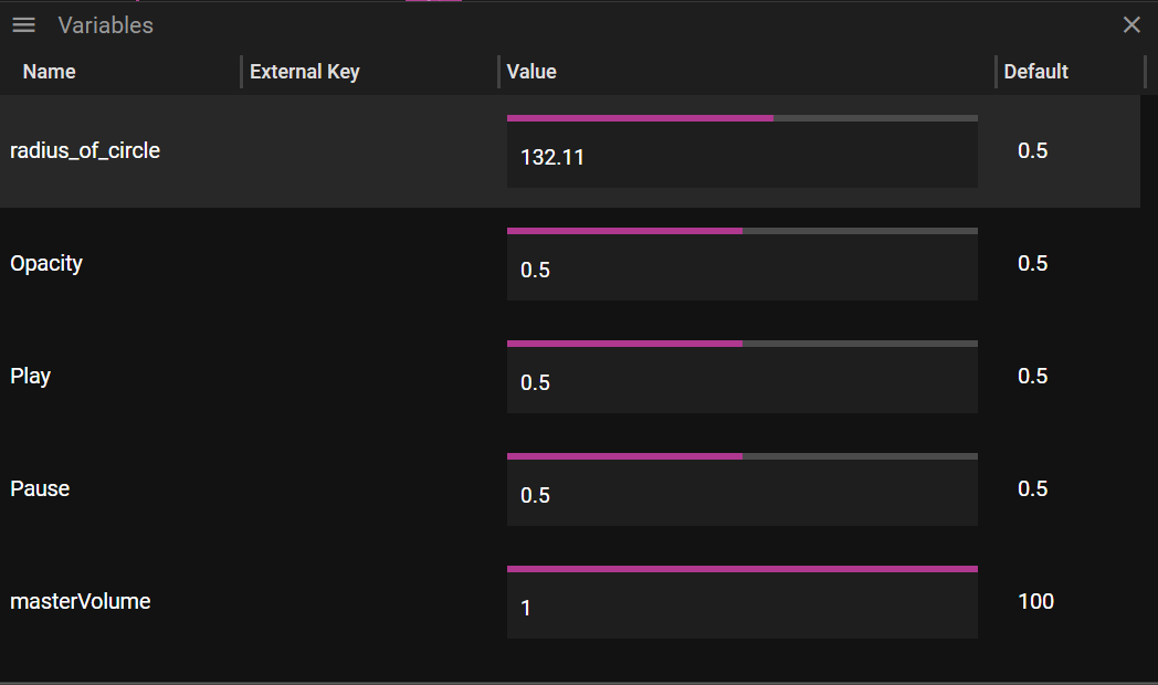
Picture above shows the Variables window. To create a variable choose Add Variable from the menu located in the upper left corner of the Variables window.
Double or single click on a variable to get to its properties.
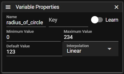
Variable properties includes
-
Name, name of variable
-
Key, input key that can be learned
-
Minimum Value/Maximum Value, minimum and maximum value the variable can have
As a guide, use these minimum and maximum values for all variables:
- 0-1 – for switches
- 0-100 – for faders
- 0-255 – for DMX
-
Default Value, the default value the variable will have at startup
-
Interpolation, the way the system interpolates between incoming values
- None, no interpolation - values change instantly
- Linear, linear interpolation that smoothly transitions between values. Input data does not always come each frame, which can cause motion to look jerky. Enable interpolation to smooth this out.
- Circular, wrap-around interpolation for rotational values. When a value needs to transition past the min/max boundary, circular interpolation takes the shorter path. For example, rotating from 350° to 10° will go through 360°/0° rather than backwards through 180°. This requires min/max values to be set correctly (e.g., 0-360 for degrees).
Tip: Click the Key column header to sort by key. With Art-Net keys like
artnet.universe(1).channel(1)throughartnet.universe(1).channel(512), sorting by key groups all channels by universe—making it easy to find your faders when managing a large lighting desk!Default variables
WATCHOUT provides a few built-in variables:
- tweenValue - The current value of a tween curve at playback position
- masterVolume - The system's master volume level
- cueVolume - the volume of an audio cue
Expressions in WATCHOUT 7
Expressions in WATCHOUT 7 provide a powerful way to create dynamic, responsive behaviors throughout your productions. They allow you to use mathematical formulas, logical conditions, and variables to control nearly every aspect of your show.
Expression Syntax
Basic Examples
"masterVolume"- Simple variable reference"tweenValue * 2"- Multiply the tween value"1"- Logical conditon that is true"0"- Logical conditon that is false"position > threshold"- Logical condition (true/false)
Formal Definition
Operators
()- Parentheses for grouping expressions^- Exponentiation (power)%- Modulo (remainder)/- Division*- Multiplication-- Subtraction+- Addition==, !=, <, <=, >=, >- Comparisons&&, and- Logical AND||, or- Logical OR
Common Functions
-
sin(radians), cos(radians), tan(radians)- Trigonometry -
min(val, ...),max(val, ...)- Value comparison -
abs(val)- Absolute value -
ceil(val),floor(val),round(val)- Rounding -
log(base=10, val)- LogarithmConstants
-
e()- Euler's number (2.718281...) -
pi()- π (3.141592...)
Creative Applications
Expressions become most powerful when combined with variables to create dynamic behaviors:
Dynamic Motion
// Horizontal oscillation
"centerX + sin(time * speed) * amplitude"

// Multi-axis floating movement
"baseY + sin(time * 0.5) * 20 + sin(time * 0.7) * 15"

// Rotation that changes based on audio level
"baseRotation + (audioLevel * rotationFactor)"
Interactive Controls
// Convert MIDI controller to position
"minPosition + (midi.ch(0).cc(1) * positionRange)"

// Smooth transition with variable
"currentValue + ((targetValue - currentValue) * smoothingFactor)"

// Cross-fade between two states
"isState1 ? masterOpacity : 0"
Special Effects
// Pulsing effect
"baseValue + (sin(time * pulseRate) * pulseAmount)"

// Progressive reveal
"progress > revealThreshold ? 1 : 0"

// Color temperature adjustment based on time of day
"baseColor + ((timeOfDay - 12) * temperatureShift)"
Best Practices
For optimal results with expressions:
- Start with simple expressions and gradually add complexity
- Test expressions with extreme input values to verify behavior
- Use parentheses to ensure correct order of operations
- Avoid division by zero by adding small safety offsets
Expressions can help enhance your WATCHOUT productions by adding responsive elements and conditional logic, making your shows more flexible and adaptable to different scenarios and environments.
Time
Overview
Keeping all nodes in a WATCHOUT show in sync is vital.
By standard, WATCHOUT uses NTP to keep the nodes in sync. This often works well on its own, but on LED installations you may need to add hardware sync.
A WATCHOUT system can be controlled externally by LTC Timecode.
Synchronization Methods
- NTP Sync
- NTP Sync with LTC
- Hardware Sync
- GenLock
- Frame Lock
NTP Sync
WATCHOUT Mode
Normally the Director node runs an NTP server. The runners are set up to follow its time. In this case NTP settings (in Nodes Window) look like this:
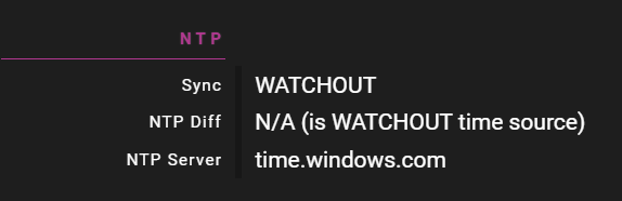
USER Mode
You may also take full responsibility for synchronization yourself. Then you need to change sync settings (in Nodes Window):
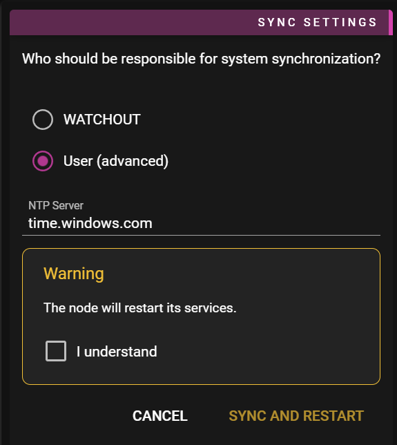
Here you can set your own NTP server. Or opt out from letting WATCHOUT handle synchronization by leaving the NTP server blank. In this case you can use any time source to keep the nodes synced, such as PTP.
If you prefer to rely on an external NTP server, Node Info looks like this:
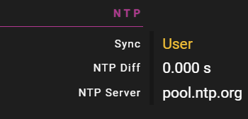
Hardware Sync
You first need to enable hardware sync on your nodes. This is done outside WATCHOUT.
There are two primary methods of hardware synchronization:
- GenLock: Synchronizes the video signal timing across devices, ensuring all outputs start each frame at the same time
- Frame Lock: A more advanced form of synchronization that ensures not just timing synchronization but that frames are displayed in perfect unison across multiple outputs
If you want true Frame Lock, you need to configure sync groups in Show Properties window:
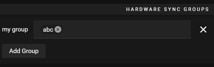
**NOTE:**If using multiple outputs on your hardware synced nodes, you may need to set up Mosaic to get it all working correctly.
LTC INPUT
LTC (Linear Time Code) is time code data encoded into an audio signal. LTC Bridge listens on a audio interface for this code, and the it controls time on at least one timeline.
LTC Bridge looks like this

Choose the input type and Host.
Timelines will show the available Timelines in the WATCHOUT show that can be controlled.
FAQ
Q. Can I control more tha one timeline?
A. Yes.
Q. Can I run many LTC Bridge applications at the same computer?
A. Yes, as long as you use different audio interfaces?
Q. What computer shall I run LTC Bridge on?
A. The LTC Bridge can run on any computer, as long as it can connect to the Director of the show.
More information about Linear Time Code (LTC) can be found on Wikipedia
OUTPUTS
There are multiple ways to output information from WATCHOUT to external systems.
The current version of WATCHOUT supports:- String output via TCP or UDP.
- HTTP output for REST APIs and web services.
- Art-Net single or multiple channel output using built-in presets.
- Art-Net single or multiple channel output using a GDTF asset file.
- Art-Net output using a pre-recorded Art-Net asset created by the WATCHOUT Art-Net Recorder.
This chapter describes the different alternatives in more detail.
STRING OUTPUT
A string output is created by right-clicking on the timeline and selecting Add Output Cue.
An output cue is represented by a box-arrow-right icon on the timeline. It can be used to send a string message over TCP or UDP.
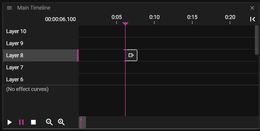
It has the following properties.
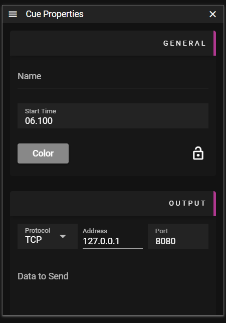
- Name Name of the Cue.
- Start Time Cue location the timeline.
- Protocol Output protocol to use, TCP or UDP.
- Port Port number to use.
- Data To Send The string of data to send. It supports all the usual backslash and escape sequences and all Unicode characters.
NOTE: 0xff are ignored.
An output string like “\xaaHej\n\tvärlden!\x10\xff” will turn out as:
aa 48 65 6a 0a 09 76 e4 72 6c 64 65 6e 21 10 ff
HTTP OUTPUT
An HTTP output cue sends HTTP requests to external systems when triggered during playback. This is useful for integrating with REST APIs, web services, lighting controllers, or any HTTP-enabled device.
Creating an HTTP Output
Right-click on the timeline and select Add Output Cue, then set the protocol to HTTP.
Properties
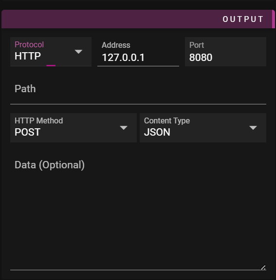
- Name - Name of the cue.
- Start Time - Cue location on the timeline.
- Protocol - Set to HTTP.
- Address - IP address or hostname of the target server.
- Port - Port number (typically 80 for HTTP or 443 for HTTPS).
- Path - URL path for the request (e.g.,
/api/command). - Method - HTTP method to use:
- POST (default) - Send data in request body
- PUT - Update resource with data in request body
- GET - Request without body (data is ignored)
- Content Type - MIME type for the request body:
- JSON (
application/json) - Default, for JSON payloads - XML (
application/xml) - For XML payloads - Plain Text (
text/plain) - For plain text data
- JSON (
- Data To Send - The content to send in the request body.
Examples
Triggering a Webhook
Send a JSON payload to a webhook endpoint:
- Address:
192.168.1.100 - Port:
8080 - Path:
/webhook/trigger - Method:
POST - Content Type:
JSON - Data:
{"event": "show_started", "timeline": "Main"}
Controlling a Device API
Send a command to a lighting controller:
- Address:
10.0.0.50 - Port:
80 - Path:
/api/v1/scenes/activate - Method:
PUT - Content Type:
JSON - Data:
{"scene_id": 5}
Simple GET Request
Trigger an action via URL (no body needed):
- Address:
192.168.0.100 - Port:
80 - Path:
/trigger?action=start - Method:
GET - Data: (leave empty)
Tips
- Use expressions in the Data To Send field to include dynamic values
- HTTP requests are sent asynchronously and do not block playback
- Connection errors are logged but do not stop the show
- For HTTPS endpoints, use port 443
Note: HTTP output does not currently support authentication headers. For APIs requiring authentication, consider using a local proxy or middleware service.
ART-NET OUTPUT
An Art-Net output can be created by using the built-in Art-Net fixture presets that give you the possibility to chose from a single (1) channel preset or a 10-channel preset.
USING ART-NET PRESETS
The 1-channel or 10-channel Art-Net fixture preset is added to the Asset window by right-clicking in the Assets window and selecting Add Art-Net fixture and then selecting 1ch Generic or 10ch Generic. You can add as many Art-Net fixture assets you want and give them unique names, or you can use a single one and create multiple cues from that one.
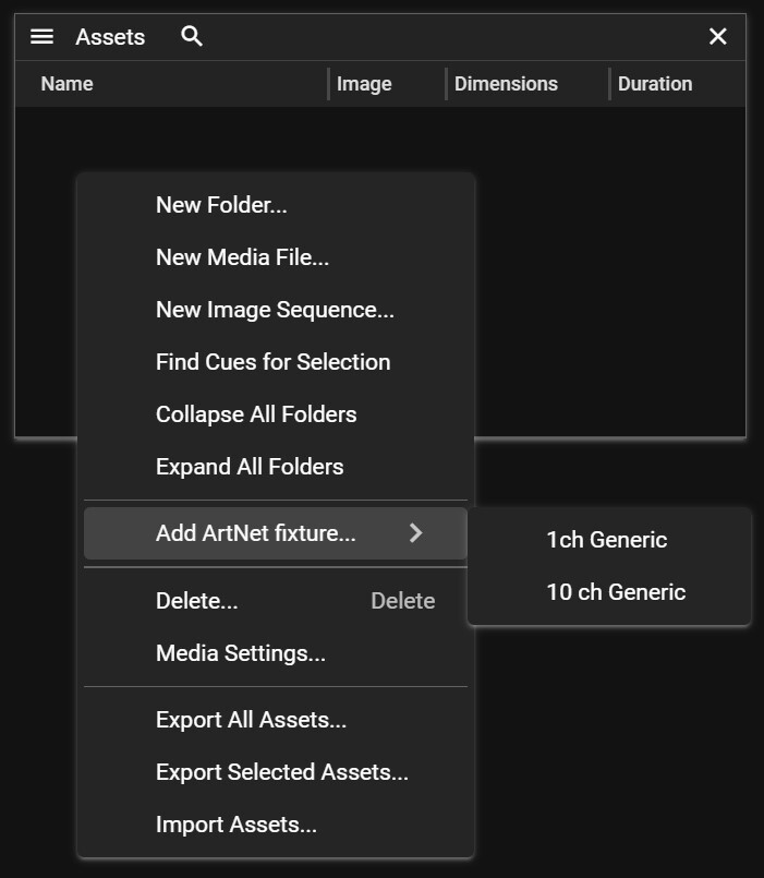
Art-Net fixture assets in the Asset window are shown below.
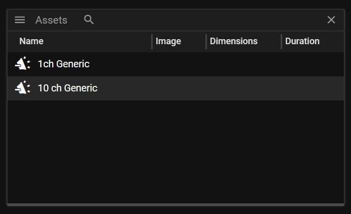
You create a cue by dragging the Art-Net asset into a timeline layer. Depending on the Art-Net asset type used you will have one or ten tween layers that can be used to manipulate the different Art-Net channel values.
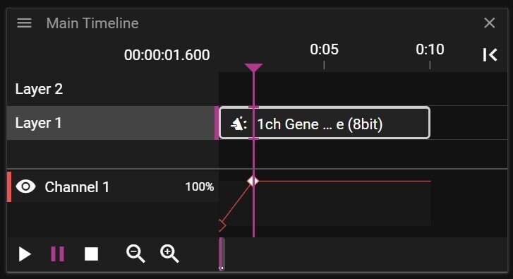
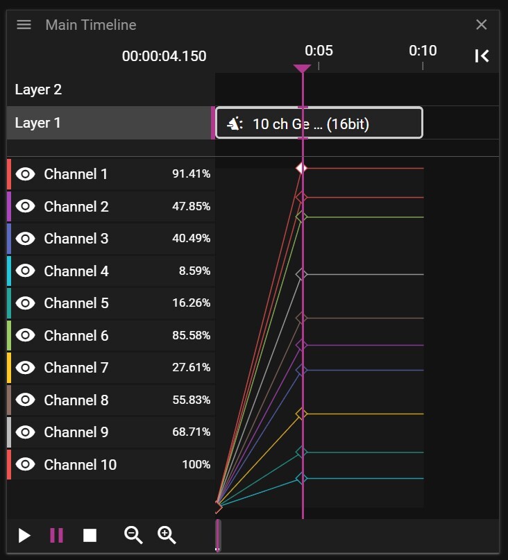
Selecting the cue will show the Cue Properties window.
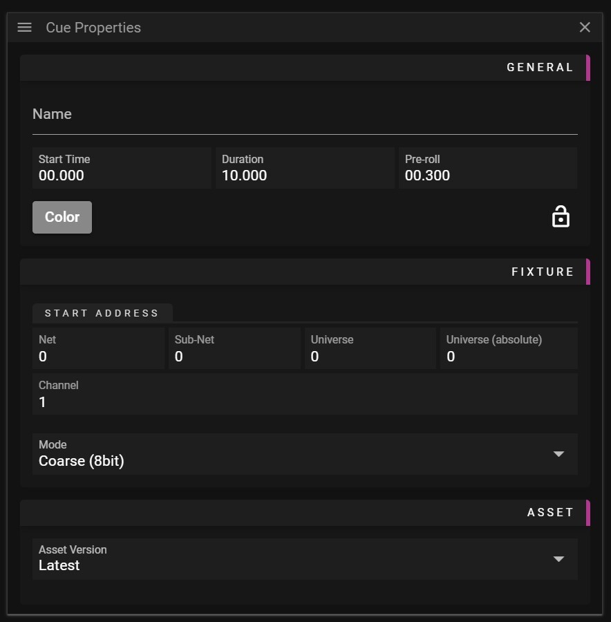
- Name Name of the Cue.
- Start Time Cue location on the timeline.
- Duration Cue duration on the timeline.
- Pre-roll Cue pre-roll time.
- Net Universe start address in steps of 256 universes.
- Sub-Net Universe start address in steps of 16 universes.
- Universe Universe start address in steps of a single universe.
- Universe (absolute) Universe start address in absolute terms.
NOTE: You can use the Net / Sub-Net / Universe to enter the Universe you want to use, and the absolute value will automatically be calculated, or you can enter the absolute address directly.
- Channel Output channel start address.
NOTE: If you use the 10-channel Art-Net preset, output channel 1 will use the channel number set in the Channel field. Output channel 2 through 10 will use the following 9 channels.
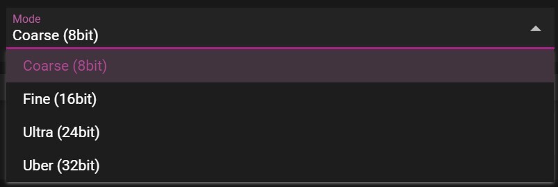
- Mode Defines the resolution of each of the Art-Net channels. The resolution can consist of 1, 2, 3 or 4 consecutive bytes grouped together to increase the resolution of the channel.
Note: Using a 10-channel Art-Net preset and a Mode set to Uber (32bit) means that each channel will reserve 4 consecutive bytes. So, output channel 1 will use the channel number set in the Channel field as a base, output channel 2 will use the number in Channel +4 as a base, output channel 3 will use the number in Channel +8 as base, etc.
- Asset Version Defines what version of the asset to use.
For more information about Art-Net, refer to Wikipedia: https://en.wikipedia.org/wiki/Art-Net
ART-NET GDTF OUTPUT
A standard GDTF (General Device Type Format) fixture descriptions file can be imported directly into the WATCHOUT Asset Manager. WATCHOUT will recognize the different GDTF channel setups in the GDTF file and let the user directly manipulate each channel's parameter individually.
For more information on the GDTF standard, and to read more about how it works, visit the GDTF homepage. There you can also search libraries for a specific fixture or create and configure your own fixture file.
USING GDTF FILE
Import the GDTF file into the Asset Manager by dragging and dropping the file into the Assets window or click in the top left menu in the Assets window and select New Media File....
This example uses a downloaded GDTF file for a Martin Professional MAC250 fixture.
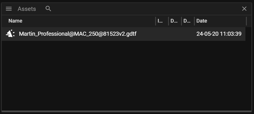
Drag the GDTF asset into a timeline layer to create a cue. Depending on the GDTF file used you will have one or more tween layers that can be used to manipulate the different Art-Net channels.
The GDTF standard allows for different values to represent different functions, which means the name shown for the different channels may change depending on the parameter value. This makes it easier to program a correct level for a function since the user can clearly see the result of a specific value, for example, if a value for a shutter is open or closed.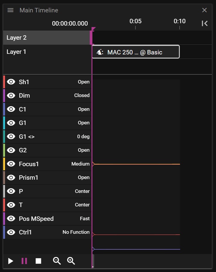
Selecting the GDTF cue will show the cue properties.
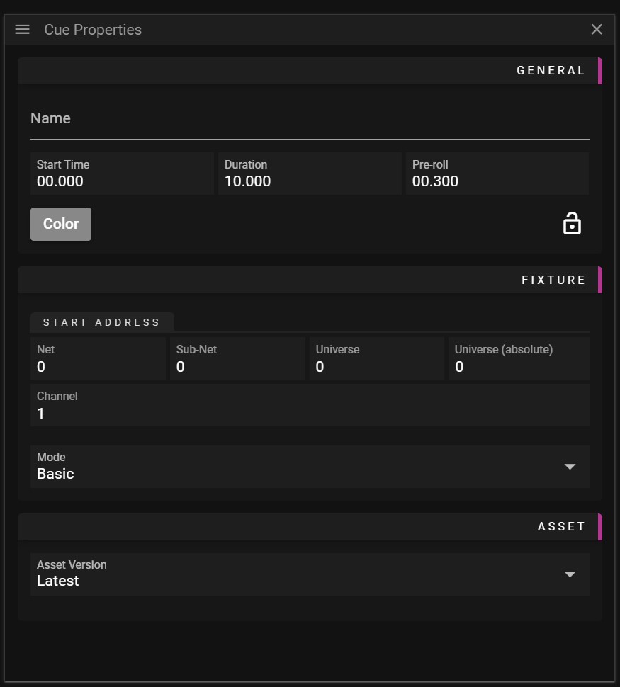
- Name Name of the Cue.
- Start Time Cue location on the timeline.
- Duration Cue duration on the timeline.
- Pre-roll Cue pre-roll time.
- Net Universe start address in steps of 256 universes.
- Sub-Net Universe start address in steps of 16 universes.
- Universe Universe start address in steps of a single universes.
- Universe (absolute) Universe start address in absolute terms.
NOTE: You can use the Net / Sub-Net / Universe to enter the Universe you want to use, and the absolute value will automatically be calculated, or you can enter the absolute address directly.
- Channel The base channel address for the fixture.
NOTE: If you are using multiple fixtures in the same universe make sure that the base address is set so you do not overlap two or more fixtures. Example: if a fixture requires 12 channels and has a base address of 1, make sure that the next fixture's base address is set to 13 or higher.
- Mode The GDTF standard allows for a fixture to have different modes. For example, a moving head has modes that require 10, 12 or 14 Art-Net channels. This is defined in the GDTF files as different modes, and the WATCHOUT user can select which of the modes to use by changing the Mode parameter.
- Asset Version Defines what version of the asset to use.
For more information about Art-Net, refer to Wikipedia: https://en.wikipedia.org/wiki/Art-Net
ART-NET RECORDING OUTPUT
An Art-Net recording is created with an external app, stored in a file, and then added into the Asset Manager's database for use as a cue on a timeline, to output Art-Net values.
WATCHOUT ART-NET RECORDER APP
The Art-Net Recorder app is used to record, in real-time, data from a specific Art-Net universe. The app is installed in the same folder as WATCHOUT and a shortcut is created on the desktop. Start the app by double-clicking on the desktop icon.
Once the WATCHOUT Art-Net Recorder is started you can start configuring the app.
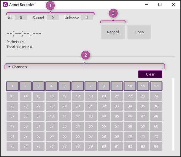
1. The settings for the Art-Net universe to be recorded are located at the top left and there are three different parameters to set:
- Net Universe start address in steps of 256 universes, range 0-127.
- Subnet Universe start address in steps of 16 universes, range 0-15.
- Universe Universe start address in steps of a single universes, range 0-15.
The resulting universe in an absolute value will be the sum of
(Net x 256 + Subnet x 16 + Universe) in the range of 0-32767.
2. The lower part shows the 512 individual channels that make up one Art-Net universe. You can select all channels or a number of individual channels to be recorded.
3. Once you have selected the channels, start the recording by pressing the Record button.
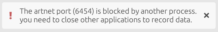
NOTE: If you get this error message when you start the app, you probably have the WATCHOUT Manager running in the background, blocking the Art-Net port. Stop the application blocking the port and re-start the WATCHOUT Art-Net Recorder to continue.
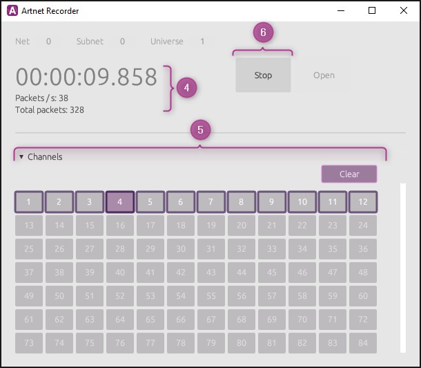
4. When the recorder is running, you can see information about recorded time, number of Art-Net packages per second and the total number of Art-Net packages recorded displayed to the left.
5. When the recorder is running, the selected recording channels will show a visual indication of the level received for each channel by changing the intensity of the color.
6. To stop the recording push the Stop button.
When the recording is stopped there are several options available next.
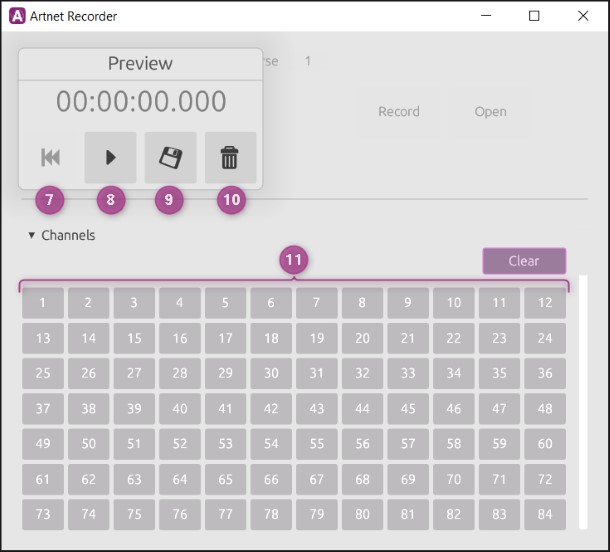
7. Jump back to beginning of recording.
8. Play the recording to preview the recording.
9. Save the recording to a file (ndjson), for later import into WATCHOUT.
10. Discard the current recording and prepare for a new recording.11. When the preview of the recorder is playing, the selected recording channels will indicate the level received for each channel by changing the intensity of the color.
As an alternative, scroll down to the bottom of the app and the recorded channels will be previewed with waveforms for a more detailed view of the recording.
USING ART-NET RECORDINGS IN WATCHOUT
Import the Art-Net recording file (ndjson) into the Asset Manager by dragging and dropping the file into the Assets window or click in the top left menu in the Assets window and select New Media File....
This is an example of how an Art-Net recording file looks like in the Assets window.
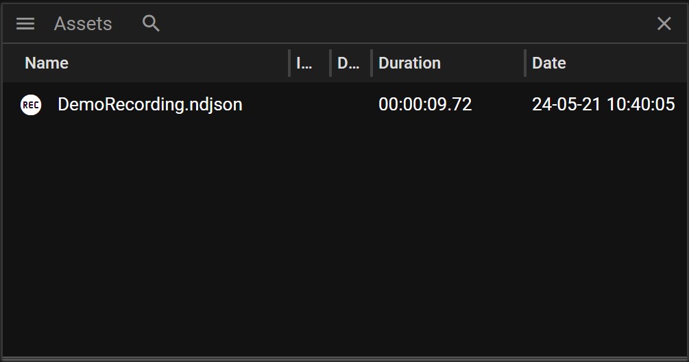
Drag the Art-Net recording asset into a timeline layer to create a cue. Depending on the number of recorded channels in the recording, you will have one or more tween layers for the cue.
You can override the maximum values of the recorded channel by manipulating the tweens of the different Art-Net channels. The value is set to 100% by default, but the value shown in the tween area on the left reflects the current maximum value that can change over time when the cue is played over.
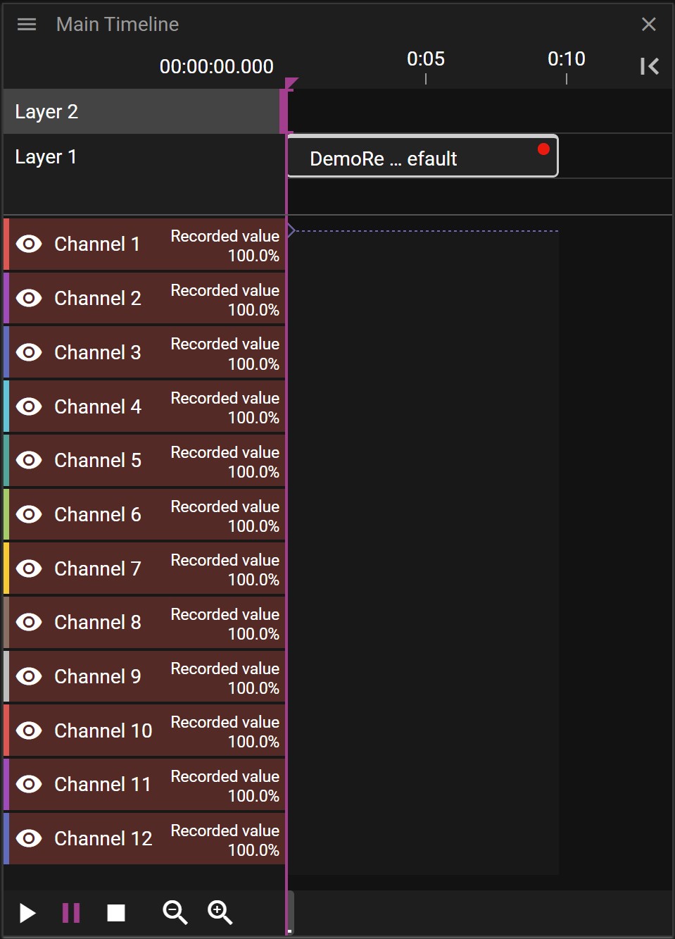
Selecting the Art-Net recording cue will show the Cue Properties.
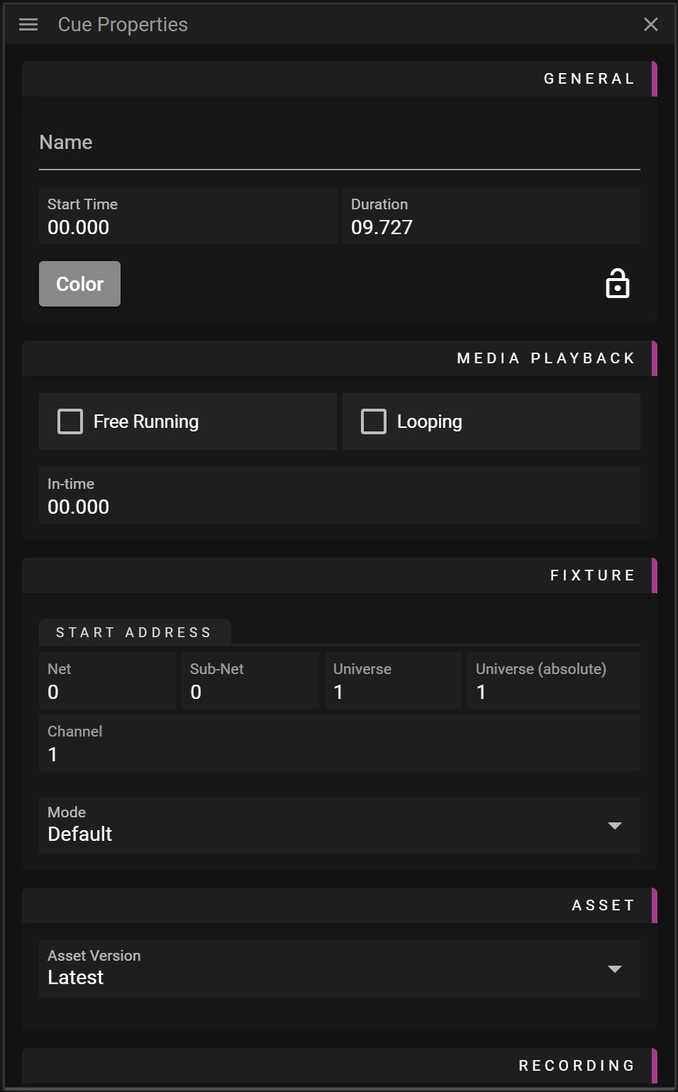
- Name Name of the Cue.
- Start Time Cue location on the timeline.
- Duration Cue duration on the timeline.
- Free Running Activates the play state of the cue regardless of the Timeline play state.
- Looping Activates looping of the Art-Net recording asset.
- In-time Defines the offset where the Art-Net recording will start playing.
- Net Universe start address in steps of 256 universes.
- Sub-Net Universe start address in steps of 16 universes.
- Universe Universe start address in steps of a single universes.
- Universe (absolute) Universe start address in absolute terms.
NOTE: You can use the Net / Sub-Net / Universe to enter the Universe you want to use, and the absolute value will automatically be calculated, or you can enter the absolute address directly.
- Channel The base channel address for the Art-Net recording cue.
- Mode Not used by the Art-Net recording cue.
- Asset Version Defines what version of the asset to use.
At the bottom of Cue Properties window for the Art-Net recording cue, there is a table that allows for changing the mapping between the recorded Art-Net channel and the Art-Net playback channel.
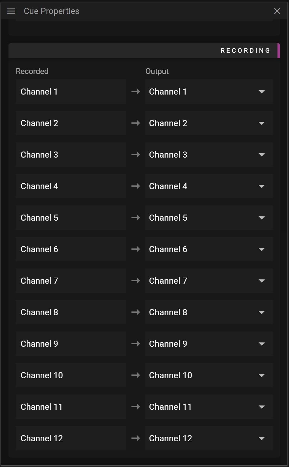
For more information about Art-Net, refer to Wikipedia: https://en.wikipedia.org/wiki/Art-Net
3D
In this chapter you will learn about working with 3D models and setting up 3D mapping using WATCHOUT.
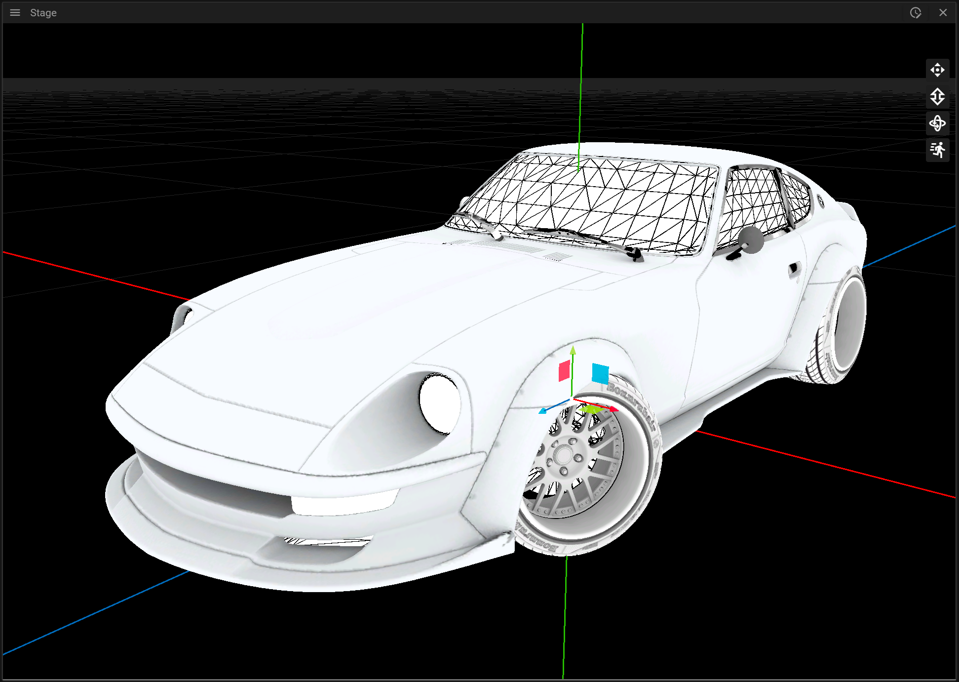
MODELS
In this section you can learn more about working with 3D models in WATCHOUT.

3D MODEL IMPORT
Producer supports import of the following file formats:
- .obj
- .gltf (or .glb)
- .3ds
If you are going to use the imported 3D model for 3D mapping it is required that the model has uv-coordinates.
3D SPECIFIC CUE PROPERTIES
There are two 3D specific properties for cues:
- Size which lets you change the size of the model.
- Surface which shows some information about the 3D asset and lets you remove media that has been applied to the 3D model.
MULTIPLE MESHES
When a 3D model is added to a Timeline a composition is created and each mesh of the 3D model is placed on a separate layer. This allows you to play different media and effects on the different meshes. The mesh names cannot be edited in Producer.
EDIT 3D MODELS
WATCHOUT has very limited 3D model editing possibilities. If you are unhappy with the mesh names or there are visual problems in the 3D model these need to be handled in a program specialized in that, like Blender etc.
3D MAPPING
3D mapping refers to projecting media to fit onto object surfaces, such as statues or cars. The process includes positioning projectors and objects in the real world, creating a virtual scene in WATCHOUT, then calibrating projectors, and projecting media. Calibration involves aligning virtual and real-world points.
To setup 3D mapping you will need:
- One or more objects to project media on.
- One or more 3D models representing the objects you want to project your media on.
- One or multiple projectors.
The setup process can be divided into the following steps:
- Position your projector(s) and object(s) you want to project on in the real world.
- Prepare a virtual scene in Producer by adding and position 3D models and projectors matching the real world from the first step.
- Calibrate each projector by trying to align the virtual scene with the real scene.
- Play media on the surface of the object(s).
In the following sections you can learn about how to prepare a virtual scene and how to align that scene with reality through a calibration step.
VIRTUAL SCENE
To prepare a virtual scene you can begin by dropping a file containing a 3D model representing the real object(s) you want to project on. It is very important that the 3D model(s) closely matches the real object(s) from a proportion perspective, otherwise it will be very hard or even impossible to perform the calibrationstep later. When the Asset Manager has finished preparing the 3D model it can be dragged from the Assets window to a layer on the timeline. It can also be dropped directly to the Stage window.
It is recommended to switch to the [First Person](../stage/stage.md#first-person) camera mode when working with 3D models since this allows you to view and inspect the 3D model freely. A model that still does not have any media/texture applied to it will be rendered using wireframe.
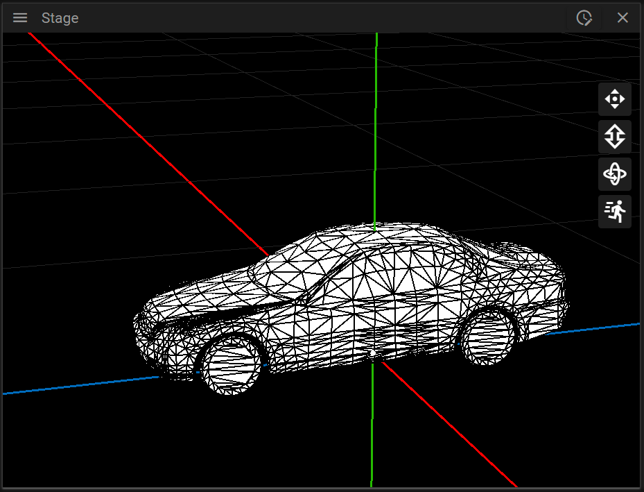
You can change the position of the 3D model by using the axis gizmo or by inputting values in the Cue Properties window.
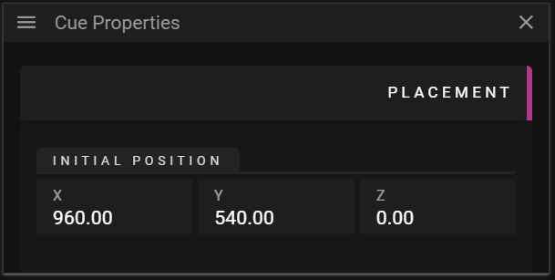
Note that the location of the 3D model in the virtual scene is not important for the 3D mapping to work, it is the relation between the virtual projector and the 3D model that is important. For instance, the 3D model can be placed far away on the x-axis, as long as the projector can “see” it from an angle matching the real-world relationship.
Once the 3D model(s) has been placed in the scene the next step is to add a projector in Producer and position the projector so it can “see” the 3D model(s). To add a projector you can right-click in the Stage window and select Add 3D Projector.
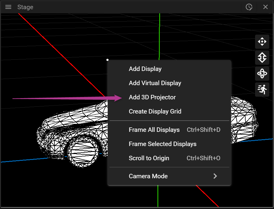
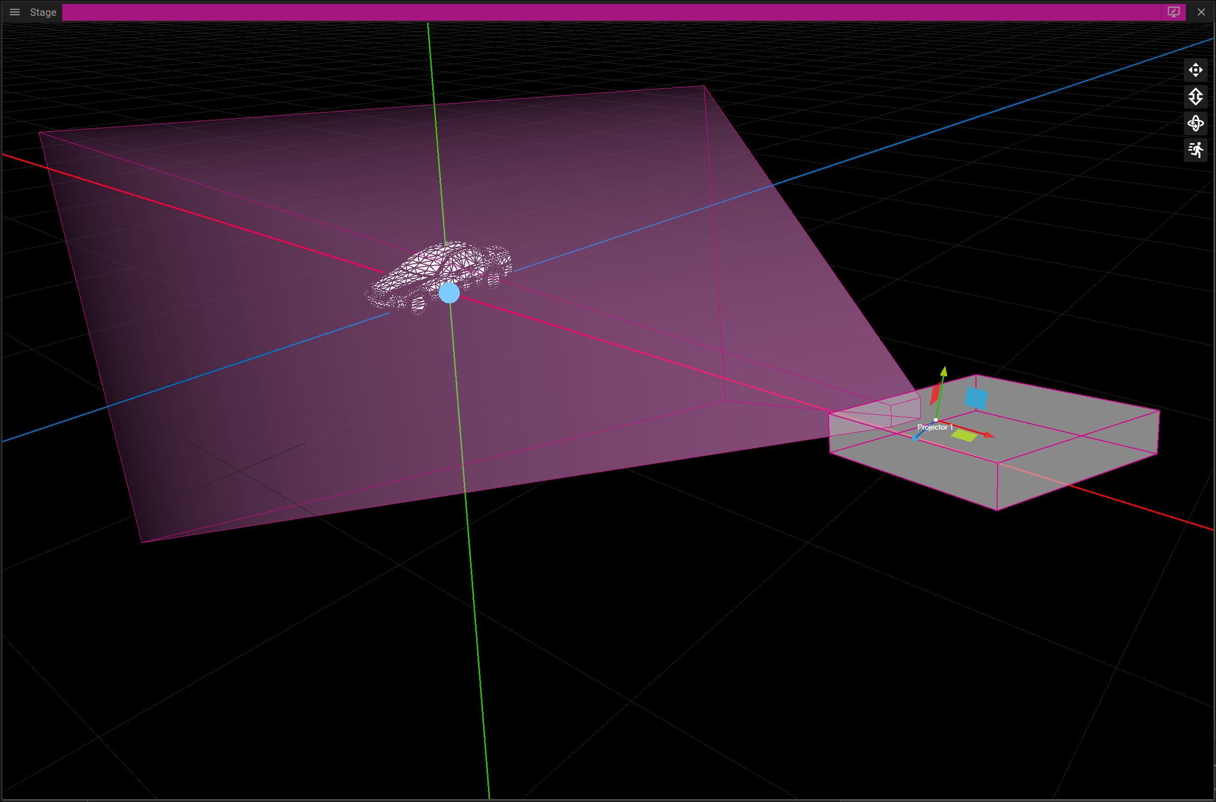
Next you can either change the Target and Eye for the projector in the Display Properties window or you can control the projector as if it was a camera. As an alternative you can position the projector by controlling it as a First Person camera.
To do this you can either click the Frame in Stage button found in the Display Properties window or by double-clicking the projector. This camera mode is referred to as Projector mode.
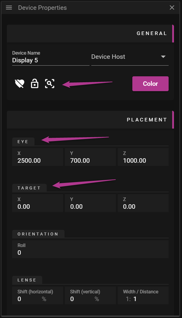
CALIBRATION
Provided you have prepared your virtual scene you are now ready to calibrate the projector. The goal with the calibration is to align virtual points with points existing in the real-world. If done correctly it is possible to seamlessly project media on top of a real object. The calibration process consists of the following sub steps:
- Place virtual points on the 3D model(s).
- Move reality points so they are at the corresponding real location on the real object.
- Align the camera to minimize the distance between the virtual and reality points.
Here is an overview of the UI:
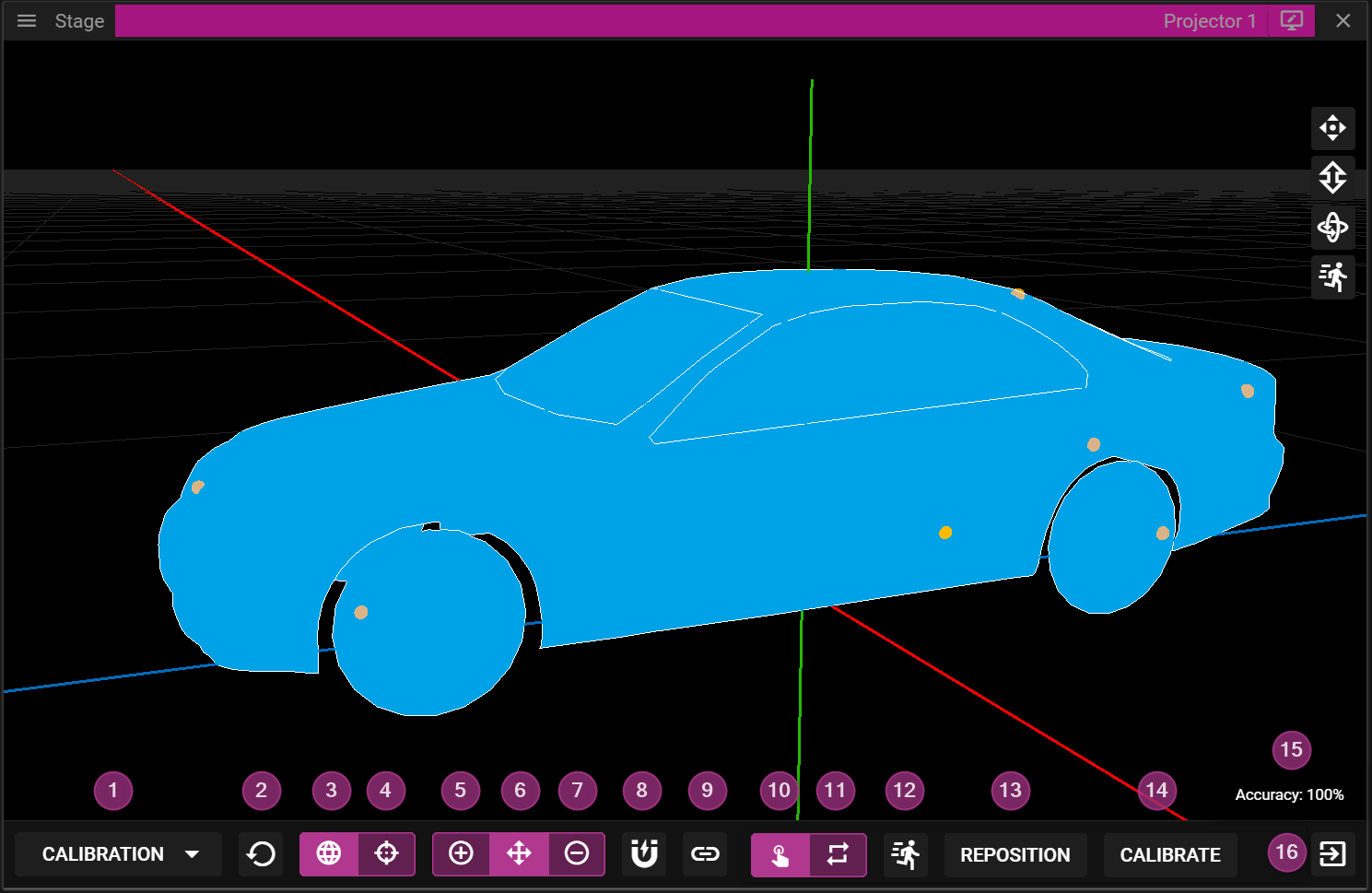
- Switch between View and Calibration mode.
- The projector may only be moved in View mode, for instance by using the W-, A-, S-, D- or arrow-keys.
- Reset the calibration.
- Edit virtual points.
- Edit reality points.
- Add points.
- Move points.
- Remove points.
- Enable/Disable vertex snapping.
- Link/Unlink the projector to the camera.
- Manual edit of calibration points.
- Update the calibration only when the calibrate button (14) is clicked.
- Continous calibration.
- When a reality point is moved the calibration is updated immediately.
- Control the movement velocity for the reality points.
- Reposition the reality points on top of the virtual points.
- Perform calibration.
- Indicates how well the calibration solution could align the virtual and the reality points.
- Exit projector mode.
VIRTUAL POINTS
There are three types of edit operations you can perform when you place virtual points on the surface of a 3D model:
- Add point.
- Move point.
- Remove point.
To add a virtual point, you need to activate the add (+) edit operation and click somewhere on the surface of the 3D model. When a point has been placed it can be moved or removed by activating the other available edit operations. To simplify placing virtual points there is a snapping option that can be enabled or disabled. When the snapping is active, adding and moving virtual points will snap to nearby vertices, basically the points that define the surface of the 3D model.
You may also unlink the projector from the camera to simplify placement of points without moving the projector. You can toggle the linked state by clicking the linked icon. When a projector is relinked to a camera the camera will move to the projector’s POV, not the other way around.
Six virtual points are required to be able to calibrate a projector successfully. More points can be added to further constrain the mapping but please note that more points does not necessarily give a better result.
REALITY POINTS
The reality points are automatically created from the virtual points. These points are not directly bound to the surface of a 3D model but since each reality point is associated with a virtual point they are indirectly bound to the surface of the 3D model.
There are two ways to edit the reality points:
- Manually.
- Continuously.
It is recommended to start by moving the points manually to give an approximation of where the points should be located. To move a calibration point you need select it by left-clicking on it (or close to it). You may also select reality points by using W-, A-, S- and D-keys or by using the left stick on a compatible gamepad. Once selected, a point can be moved by using the arrow keys or by using the right stick of a gamepad. When moving a reality point the goal is to make a virtual point on the 3D model match the corresponding reality point on the real object. For instance, if you select a virtual point located on the lower left corner of a box you want to make the corresponding reality point project on the lower left corner of the box from the real world. Once all reality points have been moved you can click Calibrate to try to align the virtual and reality points with each other.
There is a accuracy percentage label indicating of how well the system can perform this alignment of points. If the label says 100% you have perfect alignment but you can still achieve good results even with lower accuracy level.
In the manual mode it is also possible to Reposition the reality points. If you click that button you will reset reality points placed exactly over the virtual points. This may be useful if you end up in situations where the calibration gives very poor results.
During fine tuning of the calibration process, it might be helpful to activate the Continuous calibration mode. This mode will update the calibration directly when a reality point is moved. If this mode is being used when some of the reality points are far from their correct locations, you might experience severe jumps of the projector making the calibration process hard to complete. So again, only use this mode for fine tuning.
When adjusting the reality points it might be useful to hide the UI overlaying the Stage window. To do so you need to locate the button represented by an eye at the top of the Stage window. Click it to toggle the UI on/off.

AUDIO
In this chapter you will learn about working with audio in WATCHOUT.
AUDIO SHOW PROPERTIES
Go to the AUDIO BUS section in Show Properties to set the global number of audio buses in the system. You can also assign names to the different audio buses here.
Use the Count parameter to increase or reduce the number of audio buses used.
NOTE: Once you have created an Audio Device or a Audio Cue that uses a audio bus, that audio bus cannot be removed without first removing the Audio Device or the Audio Cue using the audio bus.
AUDIO DEVICES
An audio device is added by right-clicking in the Device window or by right-clicking on a specific node in the Node window and selecting Add Audio Device. The name of the audio device can be altered in the Name field.
An audio device needs to be associated with a node, if the Node entry is empty, select the node connected to the audio device from the dropdown list.
When the Node is selected and the correct Device Type (WASAPI, WASAPI exclusive, Dante or ASIO) is set, pressed the Refresh button to update the list of available Devices on the selected node. Once an audio device is chosen, parameters like channels/format/latency can be altered.
NOTE: Using a Dante audio device in WATCHOUT 7 will not work with a wireless network adapter.
If you try to select an unavailable parameter for a device, you will get an error message (!) which must be addressed.
You map the audio bus to the device's output channel in the CHANNEL MAPPING matrix. Each cross-point has a default value, indicated by a purple checkmark, set to the variable masterVolume. This can be changed to a static value, another variable, an expression or a combination of all. To open the cross-point parameter field, click on the three dots inside the square. Close the field by pressing Enter.
By default, the newly created audio device is disabled; enable the Audio Device by clicking on the heart symbol. If needed, a Runner will automatically start an Audio Renderer on the node with the Audio Device.
AUDIO CUE
An audio cue is created by dragging an audio asset into a layer on a timeline. The cue shows the name of the used asset and a rendered waveform representing the audio signal level in the audio cue.
Right-click on the cue to open its context menu. From there, you can apply effects like Fade In , Fade Out or Volume to the cue.
In the CHANNEL MAPPING section, in the Cue Properties, the routing matrix of cue channels to audio buses is set. Each cross-point has a default value, indicated by a purple checkmark, that is set to the variable cueVolume. This corresponds to the value of the Volume tween.
This can be changed to a static value, another variable, an expression or a combination of all. To open the cross-point parameter field, click on the three dots inside the square. Close the field by pressing Enter.

AUDIO VU METERS
All active Audio Devices have a corresponding set of VU meters showing the audio level for each output channel in real time. for each output channel. The VU meters are in the Nodes window, under the node connected to the audio interface.
In the Nodes window, select the node with the audio interface, expand the view by pressing the information "i"-symbol and scroll down to the AUDIO INFO property sections. If needed, click on the sections bar to expand it and the VU meters for the audio device will be visible.
If more then one audio device is active on the node, each audio device will have its own set of VU meters.
NOTE: The VU meters show the level of the signal that is outputted on the audio device, not the level on the connected audio bus. The output level depends on the parameters in the output matrix for the audio device. If different audio devices are connected to the same audio bus, the VU meters will show different levels.
AUDIO NDI CAPTURE
An NDI stream containing both video and audio can be captured on any node in the system and the node will process both the video stream and the audio stream locally.
To add processing of the NDI audio stream, you need to set up the number of incoming audio channels when the NDI capture device is created. The audio bus routing should also be set when you create the NDI capture device, and this cannot be changed after the capture device is created.
How to create and use an NDI capture device with audio, step by step:
- Right-click in the Device window and select Add Capture Device.
- Assign a relevant name to the capture device.
- Setup the Width / Hight for capture source.
- Select the NDI stream to receive in the drop-down list under ADD NDI SOURCE / Stream.
- Select the number of audio channels to receive: 1, 2, 4 or 8 channels.
- Select the Audio Latency: 20, 40, 80, 100, 200 or 1000 milliseconds.
- Set the audio bus matrix to map each NDI capture input channel to a specific audio bus.
- Press the Add button to create the stream.
To use the NDI capture device, simply drag the device from the Device window into a layer on a timeline to create a capture cue.
NOTE 1: Only NDI streams that send audio in an uncompressed format (PCM) can be used as an audio input. It will not work with NDI streams using MP3, ACC or any other compressed audio format.
NOTE 2: The audio stream is only received and connected to the audio buses on the local node. That means only a local audio device can playback the NDI audio signal.
EXTERNAL PROTOCOL
WATCHOUT offers two distinct protocols that allow external applications to control and monitor your WATCHOUT shows:
- HTTP Protocol - Modern REST-based API (recommended)For detailed documentation and examples of the HTTP protocol.
- TCP/UDP Protocol - Deprecated legacy protocol for backward compatibility Both protocols enable integration with other systems, custom control interfaces, and show automation.
HTTP Protocol Overview
The modern HTTP protocol provides RESTful endpoints to:
- Control playback (play, pause, stop)
- Navigate timelines (jump to specific times or cues)
- Load shows
- Get status information
- Manipulate cue sets
- Send inputs to variables
- Receive event streams for real-time monitoring
All requests use standard HTTP methods (GET, POST) with either JSON or plain text payloads.
Legacy TCP/UDP Protocol
The older protocol uses plain text commands sent over TCP or UDP connections. While still supported for backward compatibility, we recommend using the HTTP protocol for new integrations.
Security Considerations
Neither protocol includes authentication by default. When exposing WATCHOUT control to external networks, consider:
- Using a firewall to restrict access
- Implementing a proxy with authentication
- Keeping your WATCHOUT system on a protected network
WATCHOUT HTTP API
For complete API reference with schemas and interactive testing, visit:
http://localhost:3019/test
This document provides quick-reference examples for common integration tasks. Examples use curl syntax but work with any HTTP client. Many endpoints use timeline and cue IDs.
System
- Get Software version
curl http://localhost:3019/info
Playback
- Get Current Playback State
curl http://localhost:3019/v0/state - Play All Timelines
curl -X POST http://localhost:3019/v0/play - Play Timeline by ID
curl -X POST http://localhost:3019/v0/play/0 - Pause Timeline by ID
curl -X POST http://localhost:3019/v0/pause/0 - Stop Timeline by ID
curl -X POST http://localhost:3019/v0/stop/0 - Jump to Time (milliseconds)
curl -X POST "http://localhost:3019/v0/jump-to-time/0?time=6000&state=pause" - Jump to Cue
curl -X POST "http://localhost:3019/v0/jump-to-cue/0/0?state=pause" - Get Timelines
curl http://localhost:3019/v0/timelines - Get Timeline Cues
curl http://localhost:3019/v0/cues/0 - Send MSC (MIDI Show Control)
curl -X POST -H "Content-Type: application/json" http://localhost:3019/v0/msc --data '[{"command": {"go": {}}}]'
Inputs
- Get All Inputs
curl http://localhost:3019/v0/inputs - Set Multiple Inputs
curl -X POST -H "Content-Type: application/json" http://localhost:3019/v0/inputs --data '[{"key": "MyInput", "value": 0.5}]' - Set Input with Interpolation Duration (milliseconds)
curl -X POST -H "Content-Type: application/json" http://localhost:3019/v0/inputs --data '[{"key": "MyInput", "value": 0.5, "duration": 1000}]' - Set Single Input by Name
curl -X POST "http://localhost:3019/v0/input/MyInput?value=0.5"
Show
- Get Current Show
curl http://localhost:3019/v0/show - Load Show from JSON
curl -X POST -H "Content-Type: application/json" http://localhost:3019/v0/show --data @show.json - Load Show from .watch File
curl -X POST -H "Content-Type: application/octet-stream" http://localhost:3019/v0/showfile --data-binary @show.watch - Load Show with Name
curl -X POST "http://localhost:3019/v0/showfile?showName=MyShow" -H "Content-Type: application/octet-stream" --data-binary @show.watch - Hit Test (check if coordinates hit cues)
Returnscurl -X POST -H "Content-Type: application/json" http://localhost:3019/v0/hittest --data '{"cues": ["1/42"], "x": 960.0, "y": 540.0}'{"hit_cues": ["1/42"]}for cues hit at the given stage coordinates. Only visual media cues without conditional rendering are supported.
Cue Sets
- Get States by ID
curl http://localhost:3019/v0/cue-group-state/by-id - Get States by Name
curl http://localhost:3019/v0/cue-group-state/by-name - Switch Single Variant by ID
curl -X POST http://localhost:3019/v0/cue-group-state/by-id/<groupId>/<variantId> - Switch Single Variant by Name
curl -X POST http://localhost:3019/v0/cue-group-state/by-name/<groupName>/<variantName> - Switch Multiple Variants by ID
curl -X POST -H "Content-Type: application/json" http://localhost:3019/v0/cue-group-state/by-id --data '{"groupId1": "variantId1", "groupId2": "variantId2"}' - Switch Multiple Variants by Name
curl -X POST -H "Content-Type: application/json" http://localhost:3019/v0/cue-group-state/by-name --data '{"groupName1": "variantName1", "groupName2": "variantName2"}' - Reset All to Default (empty object)
curl -X POST -H "Content-Type: application/json" http://localhost:3019/v0/cue-group-state/by-name --data '{}'
Event Streams
Three SSE versions are available, plus NDJSON alternatives:
SSE (Server-Sent Events)
Endpoint Events Description /v0/ssePlaybackState,CueVisibilityLegacy, basic events /v1/ssePlaybackState,Inputs,ShowRevision,CueVisibilityFull state on each update /v2/ssePlaybackState(diff),TimelineCountdowns,Inputs,ShowRevision,CueVisibilityOptimized with diffs and countdowns curl http://localhost:3019/v2/sseThe
TimelineCountdownsevent provides countdown/countup timing to cues with status:Pre,Last10,Last5,Reached.NDJSON (Newline-Delimited JSON)
Same event data as SSE, but as newline-delimited JSON stream:
curl http://localhost:3019/v2/ndjsonNode Management
These commands are sent directly to individual nodes (Runners), not to the Director. Replace the IP address with the target node's address.
- Shutdown Node
curl -X POST http://192.168.1.2:3017/v0/shutdown - Reboot Node
curl -X POST http://192.168.1.2:3017/v0/reboot - Restart Node Services
curl -X POST http://192.168.1.2:3017/v0/services/restart
Appendix
Timeline and Cue IDs
Many API endpoints require a timeline ID or cue ID. These are numeric identifiers that remain stable even if you rename the timeline or cue in Producer.
To get the IDs, use Copy ID from the context menu in the Timeline window. Right-clicking a cue copies both the timeline ID and cue ID.
For example,
jump-to-cue/0/5uses timeline ID0and cue ID5.curl
curl is a command-line tool for making HTTP requests. The examples in this document use curl syntax, but any HTTP client (Postman, Python requests, etc.) can be used.
Windows Notes
Windows 10/11 includes curl, but PowerShell has a built-in alias
curlthat points toInvoke-WebRequest. To use the real curl:- Use
curl.exeinstead ofcurl - Or remove the alias:
Remove-Item Alias:curl
Single quotes in JSON don't work in PowerShell. Use escaped double quotes:
curl.exe -X POST -H "Content-Type: application/json" http://localhost:3019/v0/inputs --data "[{\"key\": \"MyInput\", \"value\": 0.5}]"Or use a here-string:
$body = @'
[{"key": "MyInput", "value": 0.5}]
'@
curl.exe -X POST -H "Content-Type: application/json" http://localhost:3019/v0/inputs --data $body
LEGACY PROTOCOL
We implemented the old version 6 protocol in order to ensure a smooth transition with as less friction as possible. We tried to keep breaking changes to a minimum and all are clearly pointed out in this chapter.
NOTE: We highly encurage you to use the new WATCHOUT protocol for new projects.
Please refer to the original version 6 documentation for a detailed listing of available commands.
DISPLAY COMPUTERS
You can control your version 7 system like controlling the WATCHMAKER in version 6. The new service Operative acts like a version 6 system and is automatically started alongside the Director
MAIN TIMELINE
In WATCHOUT 7 the concept of a Main Timline as been omitted. All timelines are treated equally. Commands previously controlling the main timline now look for a timeline called "Main Timeline". If you are using these commands make sure a timeline with this name exists.
NOTE: Timelines called "Main Timeline" are now also included in the list of auxiliary timelines.
SUPPORTED COMMANDS
Command Status gotoTime ✓ unchanged gotoControlCue ✓ unchanged reset ✓ unchanged setInput ✓ unchanged getInputs ✓ unchanged setInputs ✓ unchanged getAuxTimelines ✓ unchanged getControlCues ✓ unchanged ping ✓ changes run ✓ changes halt ✓ changes kill ✓ changes getStatus ✓ changes load ✓ changes enableLayerCond 🛇 ignored standBy 🛇 ignored authenticate 🛇 ignored online 🛇 ignored hitTest 🛇 ignored timecodeMode 🛇 ignored setLogoString ✖ unsupported serialPort ✖ unsupported getFile ✖ unsupported getStage ✖ unsupported list ✖ unsupported powerDown ✖ unsupported setRate ✖ unsupported wait ✖ unsupported CHANGED COMMANDS
ping
Response Parameter Description version 6 Changes in version 7 <string>The version of the program. -- unchanged -- <string>The name of the program. always "WATCHMAKER"<string>The name of the computer/OS. "Windows","MacOs","Linux"or"Unknown"<bool>License key is up to date. currently always true[<string>]Address of originator (empty or omitted if the origin is the conductor). always omitted getStatus
NOTE: The command takes two forms. version 7 supports both, only differences are listed here. When used without any parameter (deprecated), it provokes a responds with a Reply with the following parameters.
Response Parameter Description version 6 Changes in version 7 <string>Name of the show. Empty string if no show loaded. currently the UUID of the show <bool>Busy. always false<uint>Status of the show; 0: OK, 1: Suboptimal, 2: Problems, 3: Dead. always 0<bool>Display is open (i.e., in its full screen mode). always true<bool>Show is active (i.e., ready to run). always true<bool>Programmer is on line. always true[<uint>]Current time position, in milliseconds. Included only if show is active. -- unchanged -- [<bool>]Show is running. Included only if show is active. -- unchanged -- [<float>]Timeline rate. Nominally 1.0. Included only if show is active. always 1or0[<bool>]StandBy mode. Only included if show is active. Added in 4.1.1. always false(might change in the future)[<uint>]World time. Included only if show is active. Added in 5.2. May be very large, as the underlying data type is 64 bits. May not be entirely accurate when getStatus is used in polling mode - primarily intended for subscription mode usage. load
Request Parameter Description version 6 Changes in version 7 <string>Path to the show to be loaded -- unchanged -- [<uint>]Conditional layer enable flags, least significant bit is condition 1. -- unchanged -- [<bool>]Go online automatically. Defaults to true. currently ignored since there is no offline mode yet run, halt, kill
NOTE: In version 6 if the timeline name is not surrounded by double quotes, it reads the timeline name until the first space ignoring everything that follows eg.
run Timeline 2will try to run a timeline called "Timeline".
This has changed in that the name is always read until the end of the line.Request Parameter Description version 6 Changes in version 7 [<string>]Name of auxiliary timeline to run, pause or stop. No or empty name specifies main timeline please read the section about the Main Timeline COLOR
There are many different ways to represent colors. This chapter reviews some fundamental concepts related to representing colors in the digital world, and how to use this knowledge to make the most of colors in WATCHOUT.
OVERVIEW
Think of light as waves traveling through space; when these waves enter your eyes you may perceive colors and what colors you see, and if you see them at all, depends on the frequency of the light waves.
One way to visualize the colors that are visible to humans is by using something called a color gamut. The primary purpose of a color gamut is to convey how many colors a specific input device, like a camera, or a specific output device, like a display, can capture or present.
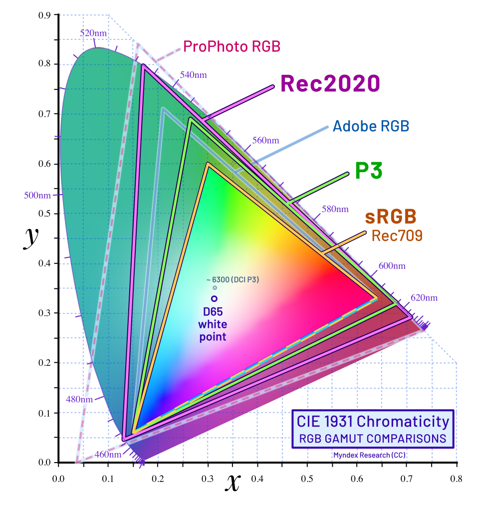
The horseshoe-shaped area of the image represents the colors, or to be precise, the chromaticities, in CIE chromaticity coordinates, that are visible to the human eye. A chromaticity is basically a color disregarding its luminance.
The colored triangles represent a subset of these colors, referred to as color spaces. For instance, there is one color space named sRGB. Although sRGB does not cover all the chromaticities visible to humans, it is still a widely used color space and works well to represent colors for a lot of scenarios.
There are other color spaces that cover more chromaticities, such as Rec. 2020. The gamut for Rec. 2020 is larger than the gamut for sRGB and can thus represent a wider range of colors. One may wonder why sRGB is ever used instead of Rec. 2020, but to represent all colors inside the Rec. 2020. gamut, without sacrificing accuracy, you would need to use more bits per pixel, ie, more data. More data means that storage will require more HD space, and it also means that more data needs to be processed during playback.
To know what color should be considered as "white" for a specific color space, the color space also defines something called a white point. In the image above there are two different white points, one labeled D65 used by Rec.2020, Rec.709 and sRGB, and another one labeled ~6300 used by DCI-P3.
The colors inside a color gamut can be represented with something called a color model, which is a numerical representation of a set of colors. One of the most common color models is RGB where you combine a red, a green and a blue numeric value to represent a color. These three individual values are also referred to as color channels.
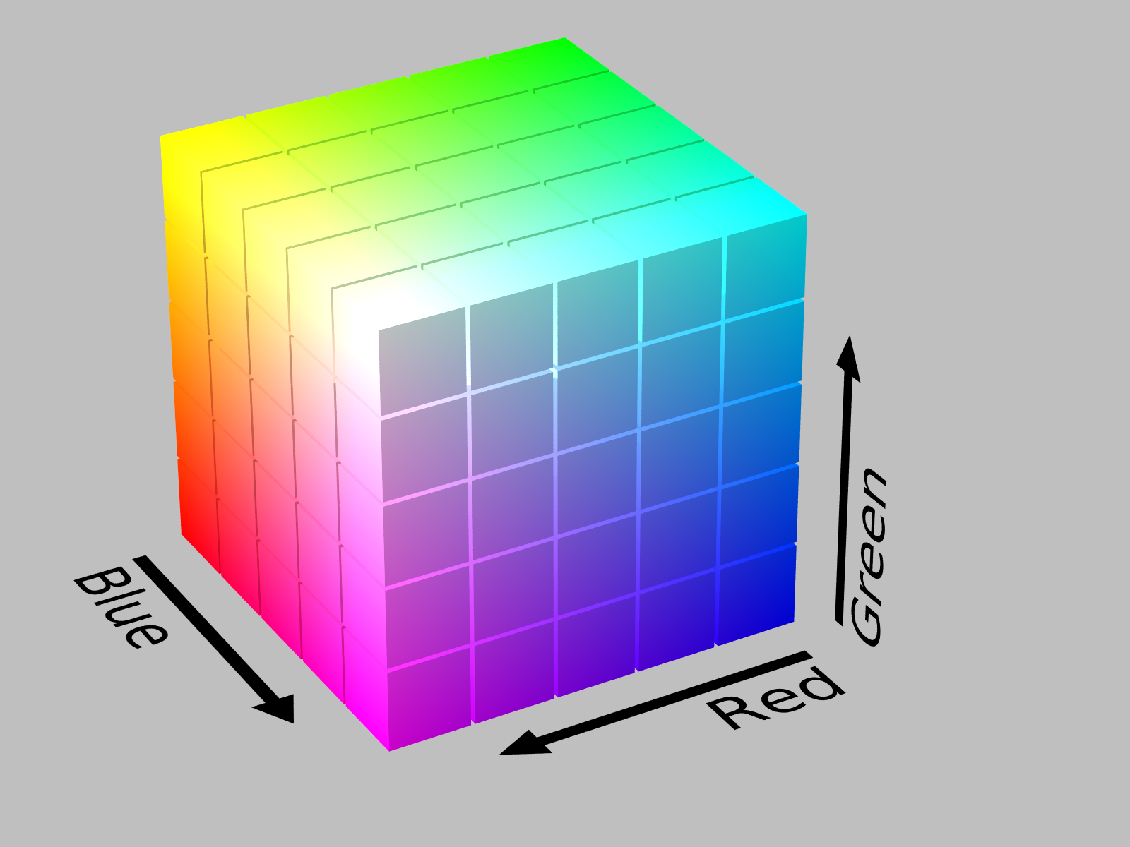
Another common color model is HSV where you combine Hue (base color), Saturation (intensity) and Value (brightness) to represent a color.
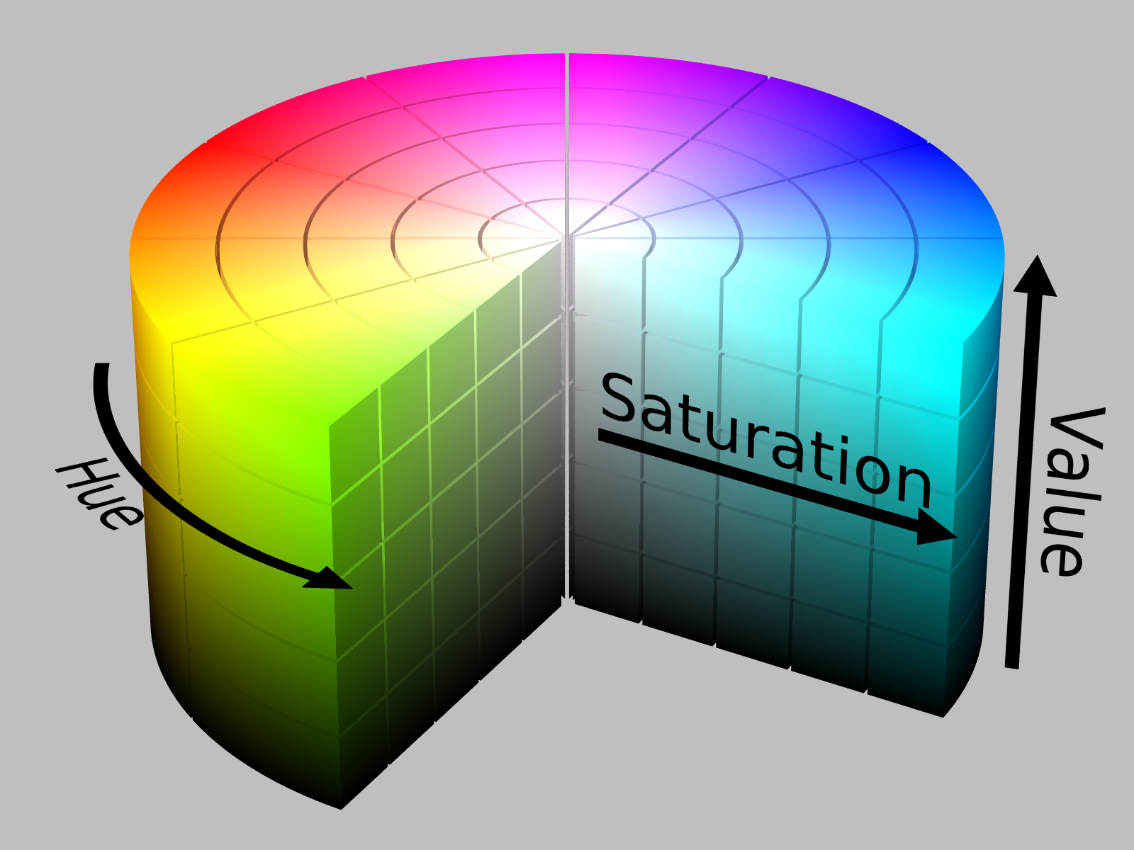
IMAGE/VIDEO COMPRESSION
As the demand for more life-like images increases, the demand for higher color depth and resolution also increases. This means that devices, such as cameras and screens, and software, such as WATCHOUT, need to invent ways to efficiently handle a larger amount of data. One way to tackle this problem is through image/video compression, which involves strategies to efficiently store the pixels of an image or the frames of a video. When working with compression there are two important concepts:
- Encoding which refers to the process of transforming color data from its original form to a more storage-efficient form.
- Decoding which refers to the process of transforming encoded color data into another form.
During encoding the accuracy of the data may decrease. This depends on which compression algorithm is used. If the algorithm is lossless, it means that no accuracy is being sacrificed. If the algorithm is lossy, it means it may remove data to pack the pixels more efficiently.
CHROMA SUBSAMPLING
The human eye is much better at perceiving variations in luminance compared to chrominance. Chroma subsampling is a compression technique that takes advantage of this fact by dividing the color information into two distinct parts, one to store the luminance of the color and another one for storing chrominance of the color.
The luminance part is usually denoted Y' where the apostrophe implies that the luma has been gamma encoded. The chrominance part, which actually consists of two components, is usually denoted CbCr and stores chroma variations.
There are different subsampling schemes and they are usually described by using a three-part ratio a:b:c (a fourth component may also exist if opacity is to be encoded), which defines how an image region is encoded.
-
a stands for the width in pixels of the region. It is usually 4.
-
b stands for the number of chrominance samples (CbCr) in the first row of the a pixels.
-
c stands for the number of chrominance changes between the first and the second row.
- The chroma subsampling region always consists of two rows.
-
4:4:4 indicates that each individual pixel in the block contains a unique color meaning that there is no data loss.
-
4:2:2 is just like 4:2:0 with the exception that two samples for chrominance changes are stored between the first and the second row.
-
4:2:0 indicates a region that is 4 pixels wide and for each of those pixels two chrominance samples are stored. There are no samples stored to express changes in chrominance between the first and the second row.
-
4:1:1 indicates a region that is 4 pixels wide and for each of those pixels one chrominance sample is stored, and 1 chrominance change sample in the first and the second row.
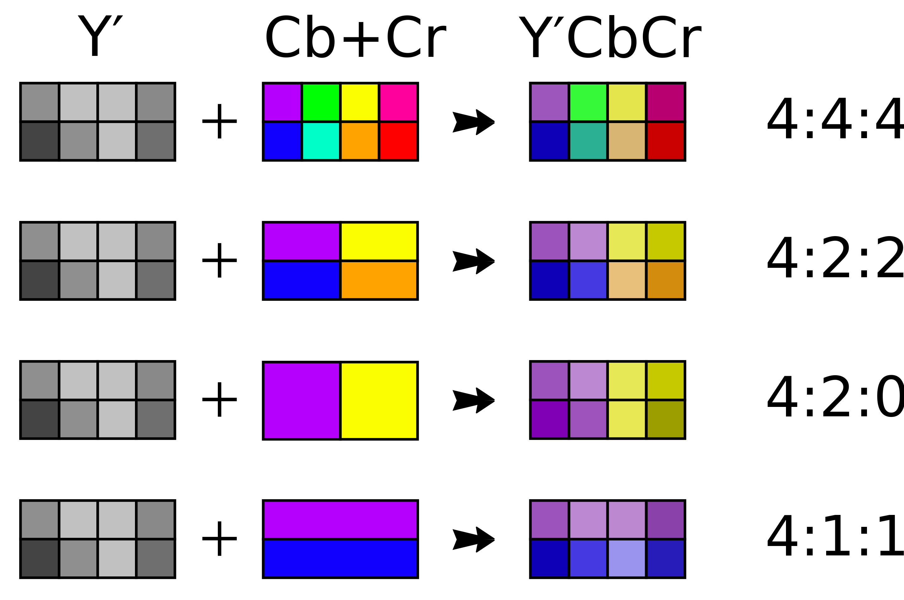
Chroma subsampling formats (License)
TEMPORAL COMPRESSION
Temporal compression looks at information between frames where consecutive frames are often very similar to each other, especially in scenes with no or gradual movement.
The video compression algorithms analyze the movement between consecutive frames to identify areas that have shifted or changed. Once identified, motion compensation predicts the current frame based on the previous frame(s) and temporal compression typically involves compressing the differences between frames rather than each frame individually.
There are different types of frames in a compressed video. There are I-frames which are complete frames meaning that all the information or pixels are there. These frames are also called keyframes, and they are encoded independently without reference to other frames. An I-frame is usually followed by one or more P-frames that store the pixels that have changed. There may also be frames called B-frames which is a special type of P-frame that looks both forward and backward for changes.
The distance between I-frames is called a Group of Pictures (GOP) A GOP consists of a sequence of frames including a keyframe (or intra-frame) followed by a series of predicted frames (inter-frames). A video from YouTube might have a GOP of 300 frames.
Media servers need an I-frame which is why, when jumping into such videos, it can take a while to get a full image and you even see the video step back.
PIPELINE
This chapter looks at how assets and their pixels, or rather colors, are transformed inside WATCHOUT. Although related to the Asset Manager chapter, this information places more emphasis on the color transformation taking place inside WATCHOUT.
Below is an overview of the different stages an asset and its pixels go through before being shown to an audience:
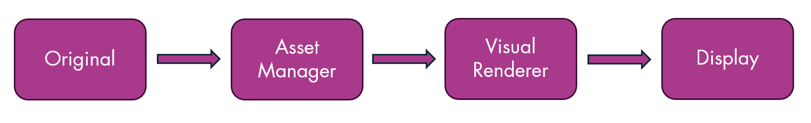
-
Original
- This is the first stage where you record/create/receive the original asset file that you want to visualize using WATCHOUT.
- WATCHOUT supports a number of file formats and codecs which you can read more about here.
- The quality of the original will have a big impact on the visual quality you can expect in the final stage.
- Factors that affect the quality are:
- Color space.
- Resolution (the number of pixels in the image or video).
- Frames per second (if it is a video).
- The type of compression, if any, that was used when the asset was created.
- Compression may reduce the accuracy of the colors in an image or video.
-
Asset Manager
- The asset reaches this state when it has been added to the Asset Manager.
- At this stage the asset can be transcoded to a different codec depending on the settings you have chosen in the Media Settings, which can be accessed from the Asset Manager file menu.
- If the asset is transcoded from a codec using a color space with a wide color gamut to a more narrow color gamut you may lose color accuracy.
- This depends on which colors are within the color space being used.
- You may also lose quality due to compression.
- It is important to understand that loss of quality might still be acceptable and a good trade-off to improve the playback performance.
- Knowledge of the system capabilities where the WATCHOUT show will be played is key to making a good decision on this.
- The settings inside Producer are deemed to be good defaults and therefore recommended. Only change these if you know what you are doing.
- The end result of this stage can be referred to as the WO asset.
-
Visual Renderer
- When the original asset has been processed and a WO asset has been created, it is ready to be sent to Visual Renderer.
- The main goal of Visual Renderer is to output color accurate pixels at the right time and as fast as possible. This process includes the following steps:
- Read the frame(s) of the asset as fast as possible.
- Multiple frames are read in parallel to assure the data is available when it needs to be presented.
- Disk and CPU clock speed, along with the number of assets that need be loaded at the same time, will affect how well this task can be performed.
- Apply effects that have been assigned to the asset.
- WATCHOUT strives to maintain color accuracy. The internal engine supports 16-bit color depth which should be enough for most use cases.
- The effects are applied in linear Rec. 2020 color space as this allows more colors to be represented. Additionally, some effects may alter the color in a way that it could not be accurately represented with sRGB for instance.
- In the Output section of the Display Properties you can select the output color depth and color space you want to use.
- It is important to understand the capabilities of your output display/projector/device.
- There is no point in trying to output colors in a configuration that is not supported by the output device.
- Read the frame(s) of the asset as fast as possible.
- Composite the pixels from an asset against assets already rendered.
- Send the pixels to the next and final stage.
-
Display
- This is the final stage of the pipeline and where the pixels are finally shown to the audience.
- As outlined in the previous stage, the output can be configured in the Output section of the Display Properties.
WHAT COLOR SPACE SHOULD I USE IN WATCHOUT?
Imagine a scenario in which you want to show a commercial in a mall on a big screen. This "big" screen consists of 8 x 8 smaller screens that must play in sync. What color space should be deployed?
The question is a bit too generic. You may have one color space for input (camera) and a completely different color space for output (display). Bear in mind that if you record using a narrow color space you generally have little to gain by using a wider color range for output, at least if the aim is to replay the content as close to reality as possible.
So to answer this question, you need to first address other key questions:
- What content do you want to show in the commercial?
- From what distance will the audience view the content?
- What color spaces are supported by the:
- Camera used to shoot the commercial?
- The screens that will be used?
- Tool/software used to process the playback?
- What frame rate and resolution do you want to use during playback and are the screens capable of reading, processing and displaying the pixels fast enough?
- What effects do you want to use and how do these effects impact playback performance?
The list goes on. As you can see there are many things that can affect this decision and it often boils down to trade-offs. For instance:
- Are you willing to sacrifice frame rate for more vivid colors?
- Are you willing to sacrifice color accuracy to be able to get smooth 60 FPS playback?
So to conclude there is no clear-cut answer to this question. Experience and experiments will guide your way.
APPENDICES
WATCHOUT KEYBOARD SHORTCUTS
GENERAL
- Ctrl-O = Open a show file
- Ctrl-S = Save show to disk
- Ctrl-Shift-S = Save show to disk with new name
- Enter = Open Properties window, if closed, or jump to Properties window
- Ctrl-Tab or Ctrl-F6 = Cycle over all open windows left to right
- Ctrl-Shift-Tab or Ctrl-Shift-F6 = Cycle over all open windows right to left
- Ctrl-F4 = Close selected window
- Ctrl-Alt-A = Open/focus Assets window
- Ctrl-Alt-S = Open/focus Stage window
- Ctrl-Alt-T = Open/focus Timelines window
- Ctrl-Alt-D = Open/focus Devices window
- Ctrl-Alt-C = Open/focus Cue List window
- Ctrl-Alt-V = Open/focus Variables window
EDIT
- Ctrl-Z = Undo
- Ctrl-Y = Redo
- Ctrl-X = Cut
- Ctrl-C = Copy
- Ctrl-V = Paste
- Delete = Delete
- Ctrl-A = Select all
- Ctrl-E = Select to end
- Ctrl-M = Move stage position of selected cues/displays
- Ctrl-F = Find
- Ctrl-N = Snap (toggle)
PROPERTY
- Tab = Move keyboard focus to next field
- Shift-Tab = Move keyboard focus to previous field
- Ctrl-Wheel = Increase/decrease value in field
- Ctrl-Shift-Wheel = Increase/decrease value in field more
- Arrow-Up (in number property) = increment value
- Shift-Arrow-Up (in number/slider/time property) = increment value more
- Arrow-Down (in number/slider/time property) = decrement value
- Shift-Arrow-Down (in number/slider/time property) = decrement value more
- Alt (while with mouse over slider property) = show bigger slider
STAGE & PREVIEW
- Ctrl-Shift-D = Frame displays
- Ctrl-Shift-O = Scroll to origin
- Alt-Drag = Zoom scale to rectangle
- Ctrl-Alt-Drag = To pan
- Ctrl-Arrow = Nudge image of selected cue 1 pixel
- Ctrl-Shift-Arrow = Nudge image of selected cue 10 pixels
- Ctrl-1 = Preview scale 1:16
- Ctrl-2 = Preview scale 1:8
- Ctrl-3 = Preview scale 1:4
- Ctrl-4 = Preview scale 1:2
- Ctrl-5 = Preview scale 1:1
CAMERA MODE NORMAL
- A = Pan left
- D = Pan right
- W = Pan up
- S = Pan down
- Wheel = Zoom in/out
CAMERA MODE FIRST PERSON AND PROJECTOR
- A = Pan left
- D = Pan right
- E = Pan up
- Q = Pan down
- W = Pan forward
- S = Pan backward
- J = Orbit left
- L = Orbit right
- I = Orbit up
- K = Orbit down
- R-Mouse-Move = Orbit around
- Arrow-Left = Move head left
- Arrow-Right = Move head right
- Arrow-Up = Move head up
- Arrow-Down = Move head down
- Wheel = Zoom in/out
TIMELINE
- Ctrl-T = Click jumps to time (toggle)
- Ctrl-P = Add play control cue
- Ctrl-Shift-P = Add pause control cue
- Ctrl-I = Insert layer
- Ctrl-Delete = Delete layer
- Ctrl-G = Group cues into composition
- Ctrl-Shift-G = Ungroup cues
- Spacebar = Start timeline (toggle)
- Esc = Pause timeline (no toggle)
- NUM 0 = Start timeline (no toggle)
- NUM x = Jump to last start position
- NUM + = Magnify timeline scale
- NUM – = Reduce timeline scale
- Ctrl-0 = Zoom to fit (or zoom to selection if items selected)
- Ctrl-Arrow-Keys = Nudge image of selected cue 1 pixel
- Ctrl-Shift-Arrow-Keys = Nudge image of selected cue 10 pixels
- Ctrl-Wheel = Scroll timeline horizontally
- Shift-Wheel= Move timeline marker 0.1 second
- Ctrl-Shift-Wheel = move timeline marker 1 second
- Arrow-Up = Select layer above
- Arrow-Down = Select layer below
- Arrow-Left = Select previous cue in layer
- Arrow-Right = Select next cue in layer
- Shift-Drag = Move a cue vertically without changing time
TABLE VIEWS
Navigate asset lists, variable tables, and other table views:
- Arrow-Up = Select row above
- Arrow-Down = Select row below
- Home = Jump to first row
- End = Jump to last row
- Page-Up = Scroll up one page
- Page-Down = Scroll down one page
- Enter = Open/edit selected item
- Ctrl-A = Select all rows
EFFECT
- Alt-Shift-I = Fade-in
- Alt-Shift-O = Fade-out
- Alt-Shift-X = Cross-fade
- Alt-P = Position
- Alt-S = Scale
- Alt-O = Opacity
- Alt-B = Gaussian Blur
- Alt-C = Crop All Sides
- Alt-Z = Rotation Z-Axis
- Alt-Y = Rotation Y-Axis
- Alt-V = Volume
DISPLAY
WARP
- Arrow-Up = Select next warp point above
- Arrow-Down = Select next warp point below
- Arrow-Left = Select next warp point to the left
- Arrow-Right = Select next warp point to the right
- Ctrl-Left-Click = When pointing at a line, add a warp point
XBOX CONTROLLER
- LEFT JOYSTICK = Move the selected point dynamically in X/Y
- D-PAD = Move the selected point exactly one pixel in X/Y
- RIGHT JOYSTICK = Select next point in X/Y, this can be central point or bezier handles points
- RB = If multiple Warp windows are open, jump to previously selected window
- LB = If multiple Warp windows are open, jump to next selected window
- X = Undo last step
- Y = Redo last step
For more information look in Appendices / XBox Controller
Terminology/Acronyms
- NUM = Keys on the number pad of your keyboard
- Arrow = The arrow keys on your keyboard
- Drag = Dragging by clicking the primary (left) mouse button and moving the mouse
- Delete = The Delete key on you keyboard, also labeled Del
(Not to be confused with backspace or **<-**) - Enter = The Enter key on your keyboard
- A - Z = Letters found on your keyboard
- F1 - F12 = The function keys found at the top of your keyboard
(On some keyboards you have to hold down the Fn key for these.) - Wheel = The scroll wheel of your mouse
XBOX CONTROLLER
You can use a standard XBox type of game controller to do the warp settings more easily and intuitively in WATCHOUT. Any controller that emulates the standard XBox model will most likely work but be aware that some controllers behave differently and may lack some of the functionality that WATCHOUT relies on.
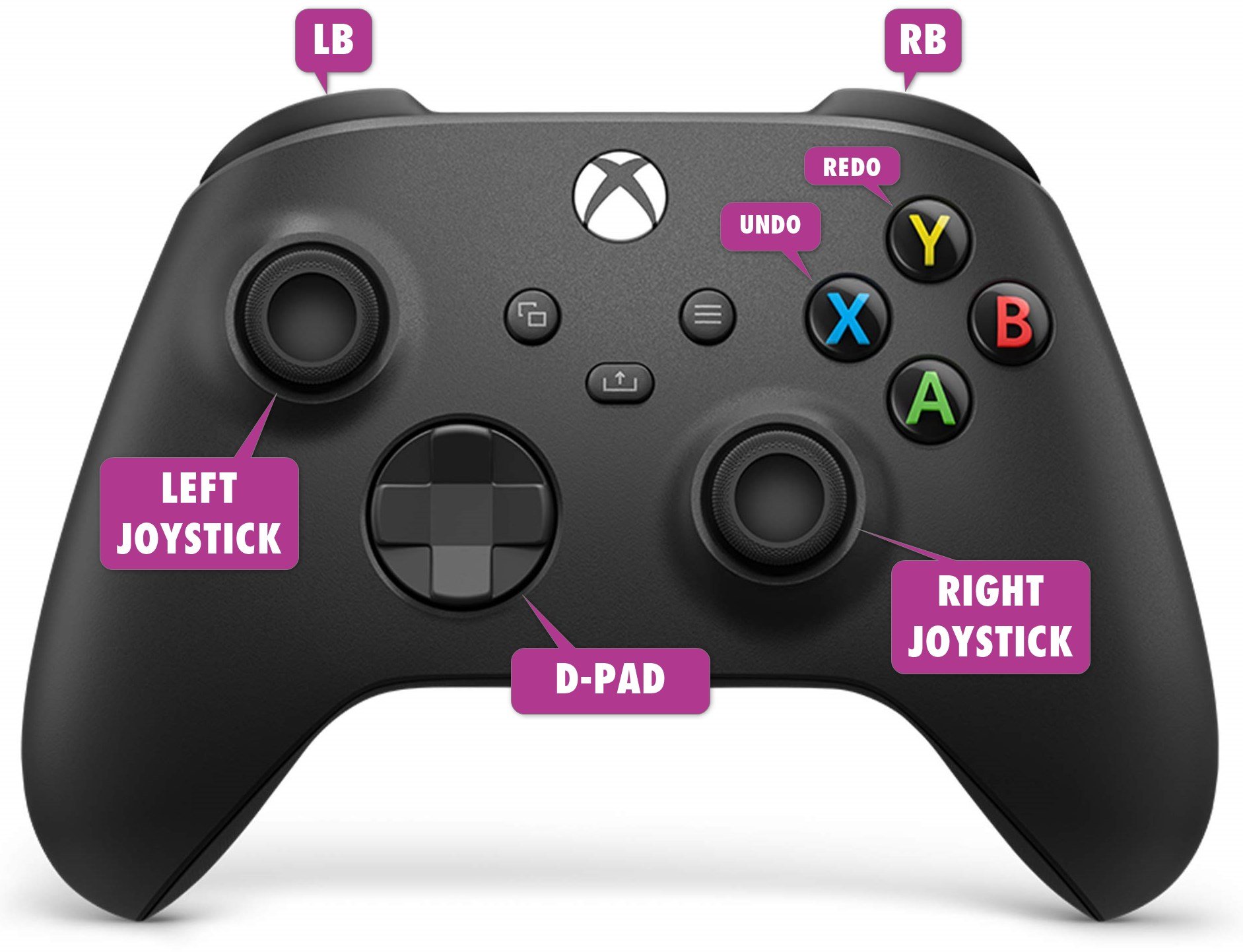
Button Action LEFT JOYSTICK Move the selected point dynamically in X/Y D-PAD Move the selected point exactly one pixel in X/Y RIGHT JOYSTICK Select next point in X/Y, this can be central point or bezier handles points RB If multiple Warp windows are open, jump to previously selected window LB If multiple Warp windows are open, jump to next selected window X Undo last step Y Redo last step NETWORK
PORTS
BASIC
Process port MANAGER 3017 RUNNER 3018 OPERATIVE INTERNAL 3020 DIRECTOR 3021 ASSET MANAGER 3023 EXTERNAL COMMUNICATION
Process port OPERATIVE EXTERNAL 3019 LOKI 3022 OSC 8000 Art-Net (DMX) 6454 LEGACY PROTOCOL 3039, 3040 MULTICAST DISCOVERY
IP 239, 2, 2, 2 QUERY PORT 3011 RESPONSE PORT 3012 HARDWARE RECOMMENDATIONS
There are recommendations for the computers running WATCHOUT Producer and WATCHOUT Manager to ensure smooth performance in show preparation and operation.
NOTE: The requirements will be updated continously.
PRODUCER
The computer running the Producer software should have the following minimum system requirements.
- Windows 10 or above
- WATCHOUT version 7 is a 64-bit application
- GPU required API is Vulkan 1.3
- CPU supported AVX instruction set
TESTED PRODUCER HARDWARE
NVIDIA GPUs
- Pascal Quadro series and later discrete GPUs
AMD GPUs
- AMD Radeon Pro Vii (driver: AMD software: Pro edition 23.Q1.1)
AMD integrated GPUs
- AMD RX Vega (AMD Ryzen 7 4700U)
- AMD Radeon Graphics (AMD Ryzen embedded V2718)
VISUAL RENDER
- Windows 10 or above
- WATCHOUT 7 is a 64-bit application
- GPU required API are openGL 4.4 / DirectX 11
- CPU supported AVX instruction set
TESTED VISUAL RENDERER HARDWARE
NVIDIA GPUs
- Pascal Quadro series and later
WATCHPAX MEDIA SERVERS
The Dataton WATCHPAX range of servers are optimized for WATCHOUT playback. WATCHPAX 40, 42, 60 and 62 media servers can be upgraded to WATCHOUT version 7. WATCHPAX servers shipped from October 2023 will have the upgrade already applied.
The WATCHOUT version 7 upgrade for WATCHPAX 40, 42, 60, 62 servers is a license upgrade and a new image file will have to be installed. Please contact Dataton or your local Premium Partner for information on this process.
WATCHPAX 64 and 30 natively supports WATCHOUT 7.
CUSTOM SERVERS
If you have an AMD graphics card, use Windows 10 as AMD has not released drivers for Windows 11, at the time of writing. If you intend to install and use Dante® then ensure there is no WIFI card, or disable any WIFI cards.
ASSET MANAGER
The Asset Manager should have a large, fast hard drive or multiple drives, as well as a GPU that supports Vulkan 1.3. This is where you store your media files which may be both large and numerous. As a rule of thumb, double up the amount of storage capacity you think you will need.
NETWORK
The computers running the Producer and Manager software must be connected using an ethernet network. A typical system has 1 Gigabit ethernet network ports on all computers and a high-quality ethernet switch with the required number of ports to connect the computers.
NOTE: A wireless network may work with WATCHOUT 7 but is generally not recommended for reliability reasons and affects synchronization accuracy among display computers. Using Dante in WATCHOUT 7 will not work with a wireless network adapter.
AUTOSTART
To setup WATCHOUT Manager to autostart on login, you can use the schtask.exe command. You need to run the command in a cmd-window with administrator privileges.
Click on the Windows logo, bottom left, and type cmd.exe, then select Run as administrator (see image below).
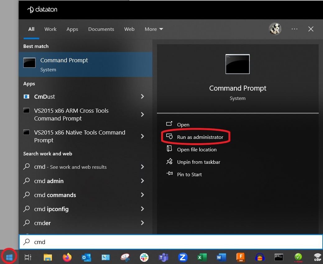
When the cmd-window is open, change directory to the WATCHOUT installation directory with the
cd C:\watchout7 command.Type this line in the cmd-window:
schtasks.exe /create /tn "WATCHOUT manager" /xml c:\watchout7\wo-autostart.xml
If you have installed WATCHOUT in a different location than c:\watchout7, edit the xml file accordingly.
To edit scheduled tasks in more detail you can run the following command:
run taskschd.msc
The wo-autostart.xml file is located in the WATCHOUT installation folder.
Enable WATCHOUT on Your Hardware
WATCHOUT runs on any Windows PC with a capable GPU. This guide covers configuration for custom-built machines and workstations—WATCHPAX systems are pre-configured.
Cloning Warning
When cloning disk images: delete the settings folder before imaging, or on each cloned machine.
Each WATCHOUT node stores a unique machine ID in
wo7_settings. Duplicate IDs cause identification conflicts in your cluster.Settings folder location:
- Custom servers:
C:\Users\<username>\AppData\Roaming\Dataton\WATCHOUT 7\
Software Update Allowlist
Software updates are disabled by default for security. You must explicitly enable them.
Create
allow_list.jsonin your WATCHOUT settings folder:{ "folders": ["D:/shows/"], "update_allowed": true }Without this file, Producer cannot push software updates to your machines.
Field Purpose foldersPaths accessible for asset transfer update_allowedSet trueto allow remote software updatesTo find the settings folder: File → Explore Settings Folder in Producer.
WATCHPAX systems are pre-configured.
Requirements
- Latest graphics driver
- Media Feature Pack (Windows N/KN editions only)
Hardware
WATCHOUT puts sustained load on SSDs and GPUs. These components can throttle or overheat.
- Use enterprise-grade SSDs for 24/7 installations
- Ensure adequate GPU cooling
- Monitor temperatures during extended testing
Software Optimization
- Minimize background programs
- Disable notifications and popups
- Kill Explorer if needed:
taskkill /im explorer.exe /f
Display Channel Numbering
Windows can re-number display outputs when connections change. To lock physical GPU connectors to fixed channel numbers, set this environment variable:
USE_GPU_CONNECTORS_AS_CHANNELS=TRUERestart WATCHOUT after changing.
Video Capture
Supported interfaces:
Interface Notes Deltacast VideoMaster GPU-direct capture (NVIDIA only). HDMI/SDI boards only. Windows Media Foundation USB devices, Magewell, Datapath. Performance varies. NDI Network-based capture. Interlaced Video
WATCHOUT de-interlaces by interpolating missing lines. Deltacast and NDI provide lower-latency interlaced fields. Media Foundation typically de-interlaces in hardware or delivers at half framerate.
Tested Hardware
- WATCHPAX systems
- Magewell Pro Capture Quad SDI (driver V1.3.0.4323, firmware 1.34)
Legal Notices & Support Resources
Dataton WATCHOUT ® software and this introduction © Copyright 2023 DATATON AB (“Dataton”). All rights reserved.
Dataton, the Dataton logo, WATCHOUT and WATCHPAX are registered trademarks of DATATON AB. All other company and product names are trademarks or registered trademarks of their respective owners. Use of a term in this publication should not be regarded as affecting the validity of any trademark.
Dante is a registered trademark of Audinate Pty Ltd.
NOTCH is a registered trademark of 10 bit FX.
The information in this guide has been carefully checked and is believed to be accurate.
However, Dataton assumes no responsibility for any inaccuracies or errors in this manual or the products described. In no event will Dataton be liable for direct, indirect, special, incidental, or consequential damages resulting from any defect or omission in this manual, even if advised of the possibility of such damages. The technical information contained herein regarding features and specifications is subject to change without notice. Products or manufacturers mentioned do not constitute a recommendation or endorsement by Dataton.
User forum https://forum.dataton.com
Knowledge Base https://knowledge.dataton.com/knowledge
If you have an issue and need to contact the support department, please visit the Help Center and submit a support ticket. https://www.dataton.com/helpcenter
Document version 7.7.1 rev 01, 2026-03-11
GLOSSARY
This section lists some common terms that are used when working in WATCHOUT.
ALPHA CHANNEL
Refers to a color channel that stores information on the transparency or opacity of a pixel. If the alpha value is set to 0 (zero) it is completely transparent and if it is set to 1 (one) it is opaque.
AUDIO BUS
An audio bus is a virtual mono path collecting tracks from one or more audio cues and transmitting onto one or more output device channels. The available buses in the system are numbered from 1 and upwards, but can also be assigned names. By default buses 1 and 2 have the names Left and Right. The available buses are visible in the channel mapping sections of the Cues and devices.
AUDIO DEVICE
An audio device is a device capable of playing sound. An audio device is controlled by a Runner, and can be of type WASAPI, WASAPI exclusive, Dante or ASIO. A WASAPI, WASAPI exclusive or ASIO device is always hosted on the same machine as the Runner, either built-in, or connected via USB. A Dante device is attached to the network, but controlled by a Dante controller on the Runner's device. An audio device can have one or more channels.
AXIS GIZMO
An axis gizmo is generally used to move, scale and rotate objects in 3D editors.
BITS PER PIXEL
Refers to the number of bits used per pixel, which is shortened as bpp. If an image consists of pixels that use 8-bits per channel, and there are three channels per pixel, it is considered to be a 24 bpp image.
CHANNEL MAPPING
Channel mapping is the process of mapping audio cue channels to audio device channels. This is done in two stages: first in the Cue properties window where the cue channels are mapped to audio buses, then in the Audio Properties window, where the audio buses are mapped onto audio device channels.
CHROMATICITY
Refers to the color without taking into account luminosity.
CHROMINANCE
Refers to the color in relation to luminosity.
CODEC
Refers to a device or software that can be used to encode and decode a data stream.
COMPRESSION
Refers to techniques used to reduce the size of data, such as an image or video.
COLOR BIT DEPTH
Refers to the number of bits used per color channel for a pixel. If a color channel consists of 8-bits, each channel can represent 256 different values. Three 8-bit channels can represent 256^3=16777216 different colors. This value is referred to as the color depth.
COLOR CHANNEL
Refers to a specific component of a color model. RGB consists of a red, green and blue channels.
COLOR DEPTH
Refers to the number of colors that can be represented in an image. It is often used to convey how many colors a specific input/output device can handle and is related to color bit depth.
COLOR GAMUT
Refers to all chromaticities that can be represented by a specific output or input device.
COLOR MODEL
Refers to a numerical representation of a color. Examples include RGB, HSV and CMYK.
COLOR SPACE
Refers to a constrained space in which you can represent a set of colors. Examples include sRGB and Rec.2020.
EDID
Stands for Extended Display Identification Data which is used to share display properties between different devices. For instance, it can be used to let a GPU know what computer screen is currently connected.
GAMMA CORRECTION
The human eye is much better at perceiving differences between dark colors compared to bright colors. This is exploited when storing and displaying image data. The concept called gamma correction may refer to both gamma encoding and decoding.
GAMMA ENCODING
Refers to transforming image data in a way where more bits (more data) is used for darker colors and fewer bits (less data) is used for brighter colors.
GAMMA DECODING
Refers to reversing the gamma encoding operation which means a color is transformed from its encoded value to its original value.
HDR
HDR, which stands for High Dynamic Range, refers to a set of techniques that allow for a greater range of luminance levels between the darkest and brightest parts of a video image compared to standard dynamic range (SDR) video.
LOSSLESS COMPRESSION
Refers to a compression technique that reduces the size of data, such as an image or video, without sacrificing any quality.
LOSSY COMPRESSION
Refers to a compression technique that reduces the size of data, such as an image or video, where quality/accuracy is often sacrificed for greater reduction in size.
LUMA
Refers to the brightness or grayscale intensity of an image.
LUMINANCE
Refers to a photometric unit used to describe the brightness of light.
MESH
A mesh is a surface composed of a set of connected polygons.
NODE
A machine that runs WATCHOUT software. In a WATCHOUT system, nodes can function as display computers, audio playback machines, or control servers. Nodes communicate with each other over a network to create synchronized multimedia presentations.
POLYGON
A polygon is a surface defined by three or more vertices. In WATCHOUT each polygon is always a triangle and thereby defined by three vertices. Sometimes polygons are also referred to as faces or triangles.
SDR
SDR, which stands for Standard Dynamic Range, refers to the standard range of luminance levels between the darkest and brightest parts of a video. It cannot represent the same amount of color detail compared to a high dynamic range (HDR) video.
TEXTURE
A texture can be thought of as an image that is to be applied to a mesh surface.
UNIFORM SCALING
Uniform scaling means that x, y and z are scaled equally.
UV-COORDINATE
UV-coordinates are used to map an image/texture onto a polygon. UV-coordinates are also sometimes referred to as texture coordinates.
VERTEX
A vertex is a point in space. Three vertices form a triangle/polyon in a mesh.
WHITE POINT
Refers to a point in a color gamut that is used as a reference color for white.
WIREFRAME
Wireframe rendering means that each polygon edge is rendered as a visible line. The intention with this render mode is often to get a better understanding about the topology and polygon density of a mesh.