
PREFACE
Dataton WATCHOUT ® software and this introduction © Copyright 2023 DATATON AB (“Dataton”). All rights reserved.
Dataton, the Dataton logo, WATCHOUT and WATCHPAX are registered trademarks of DATATON AB. All other company and product names are trademarks or registered trademarks of their respective owners. Use of a term in this publication should not be regarded as affecting the validity of any trademark.
Dante is a registered trademark of Audinate Pty Ltd.
NOTCH is a registered trademark of 10 bit FX.
The information in this guide has been carefully checked and is believed to be accurate.
However, Dataton assumes no responsibility for any inaccuracies or errors in this manual or the products described. In no event will Dataton be liable for direct, indirect, special, incidental, or consequential damages resulting from any defect or omission in this manual, even if advised of the possibility of such damages. The technical information contained herein regarding features and specifications is subject to change without notice. Products or manufacturers mentioned do not constitute a recommendation or endorsement by Dataton.
User forum https://forum.dataton.com
Knowledge Base https://knowledge.dataton.com/knowledge
If you have an issue and need to contact the support department, please visit the Help Center and submit a support ticket. https://www.dataton.com/helpcenter
Document version 7.1.2 Rev 01
THE BASICS
Producer is a desktop application that lets you transform your creativity into WATCHOUT shows. The goal with this chapter is to give you an overview of Producer along with a brief introduction to some fundamental concepts.
WELCOME SCREEN
When you start Producer you will be greated with a welcome screen which allows you to open existing shows or create new ones. You may also connect to an already running show.
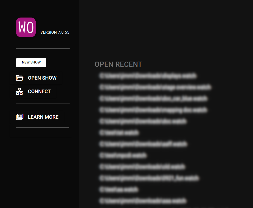
- New Show creates a new show on the Director currently in use. If no Director is currently being used by Producer a new show on the local node will be created.
- Open Show opens the selected show and tries to connect to the Director and Asset Manager that was used when the show was saved.
- Open Recent lists shows that you recently worked on.
- Connect opens a dialog allowing you to select the Director you want to connect to. The show on the selected Director will be loaded in Producer.
- Learn More opens a page where you can learn more about the products and services that Dataton provides.
- Your Feedback creates a feedback report for the Dataton team which they can use to understand any issues you may have encountered when creating or playing a show.
You can learn more about the Director, Runner(s) and the Asset Manager in the setup chapter.
WINDOWS
All WATCHOUT windows reside inside a desktop window, indicated with the WO icon and the word Producer. You can resize the desktop window by dragging any of its outer borders or corners. Minimize or maximize it using the buttons in the upper right corner. Clicking the close box is equivalent to choosing Quit on the File menu.
Move a WATCHOUT window by dragging its title bar. Resize a window by dragging any of its corners or outer borders.
When you open the Producer, you will see a number of windows.
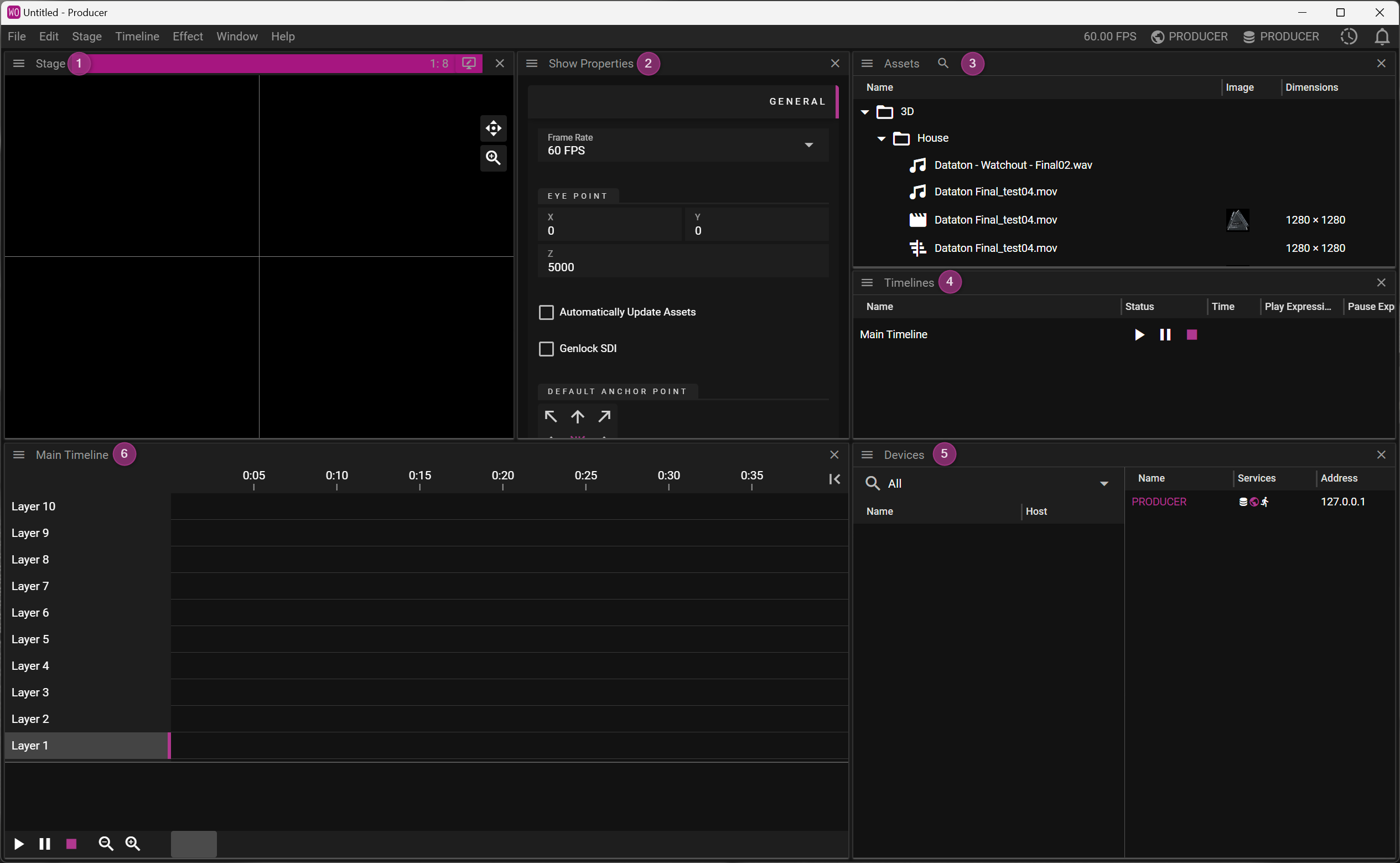
- The Stage window shows the display areas and a preview of the presentation.
- The Properties window is context-dependent and in this initial layout shows the show properties.
- The Assets window lists all media used in your presentation.
- The Timelines window lists the timelines used in the show.
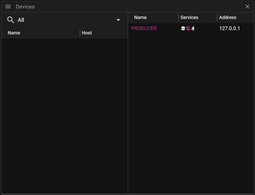
- The Devices window gives info on the devices on your network.
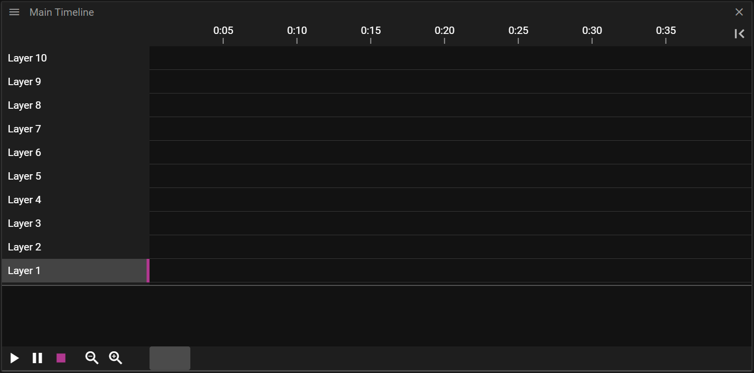
- The Main Timeline presents the layers, cues and effects in the show
Windows are opened or re-opened through the Window menu. Double-click on a timeline in the Timeline window to open its window.
WINDOWS LAYOUTS
Window layouts can be reset, saved and loaded from the Layout submenu of the *Window menu.
To save a layout, choose Layout from the Window menu and select Save. Enter the file name, select the location and save.
To load a layout, choose Layout from the Window menu and select Load. Locate the saved layout on your computer and select Open.
To reset the layout to the default layout (as seen when creating a new show), choose Layout from the Window menu and select Reset.
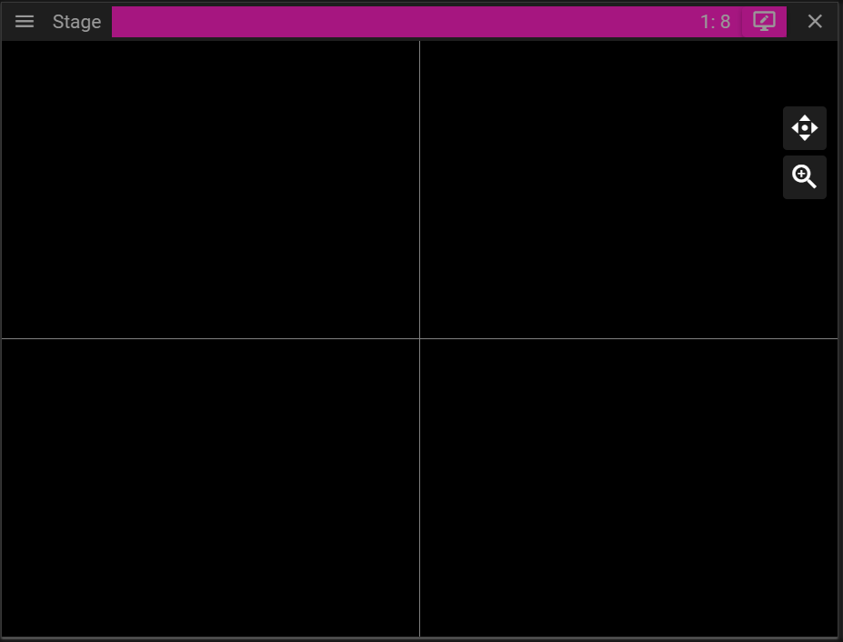
STAGE WINDOW
The Stage window is where you set up your presentation layout and add your display devices.
If you are new to WATCHOUT, think of the Stage as a large canvas, where you can add media files – video, still images, audio files and various input and output items. Displays, whether physical such as an output from a graphics card on the display server, an NDI output from the display server, a virtual display or a 3D projector can all be regarded as windows on that content.
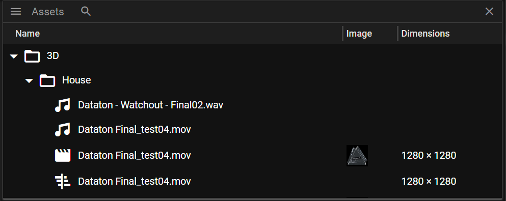
ASSETS WINDOW
This is where your media files are available to use. Media files are not loaded into the WATCHOUT show file, but are stored in the Asset Manager which makes them available for the media servers and the Producer for programming. In previous WATCHOUT versions the Assets window was known as the Media window.
TIMELINES WINDOW
This is where the media files are placed and played back. A Timeline is linear, playing back content over time from A to B. WATCHOUT supports multiple Timelines which run simultaneously if required.
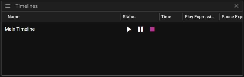
The Main Timeline is shown by default when you first open the Producer and you can choose to keep it visible, rename it, hide it or delete it. You can easily add new timelines to suit your show setup under Timeline on the top menu and the Timelines window menu.
DEVICES WINDOW
This is a new feature in WATCHOUT and lists all available nodes in the WATCHOUT ecosystem. From this window, you can enable services such as Producer or Asset Manager as well as adding displays, audio devices (such as Dante®) or an NDI® video source.
You can learn more about devices here.
PROPERTIES WINDOW
The Properties window is context-sensitive and displays information related to the window or item that is currently selected. For example, if you click on a file listed in the Assets window, the properties of that file will be displayed in the Properties window (Name, Type, Frame Rate, etc). if you click on a timeline in the Timelines window, timeline properties will be displayed (Name, Duration, and any Triggers that have been applied, etc).
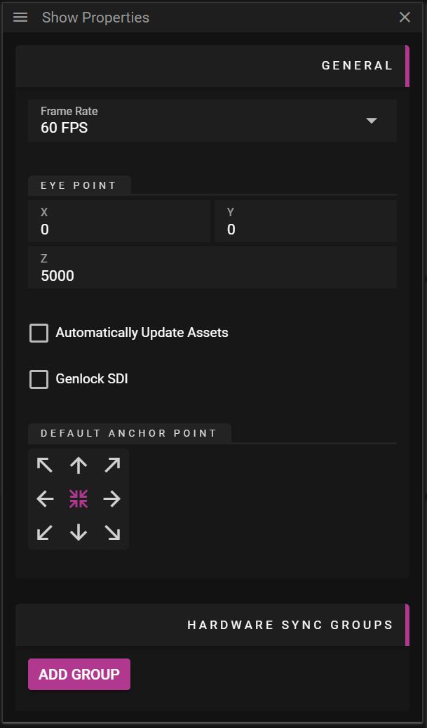
SHOW PROPERTIES WINDOW
When this window is active you can set the frame-rate for your WATCHOUT show and enable automatic update of media assets.
ACTIVATING NODES
You have to activate the various sevices (Director, Asset Manager, etc) before you can start to make your show. The Producer will discover the nodes available on the network. In the example below, there is a single node called Producer (the PC that is running the WATCHOUT software). The PC had this name assigned in Windows but you can also assign a name in the Device Properties window. Please note that the system will need to be restarted in that case.
To activate the various nodes, go to the Devices window and right-click on the relevant node – in this case Producer.
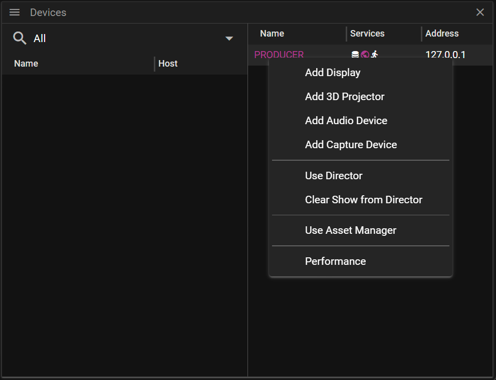
Click on Use Director. The services list in the Device Properties window will show it has become active.
Now do the same for the Asset Manager.
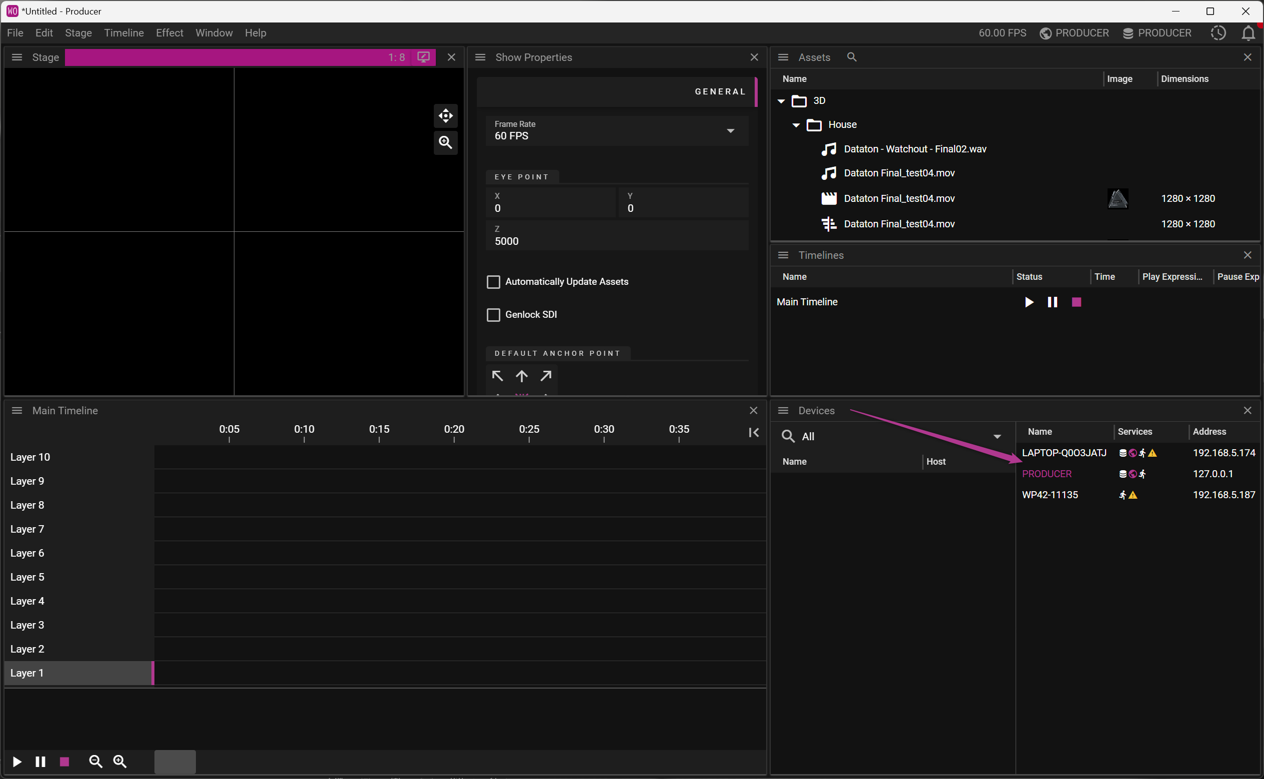
In the screen above, we have added more nodes to the WATCHOUT system. Note that WATCHOUT network discovery now finds a node running the WATCHOUT software with an IP address in a different range.
You can assign roles by right-clicking on a node.
SETUP
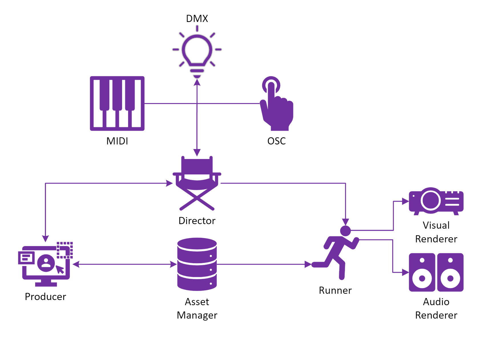
The purpose of this chapter is to give an overview of how you can set up a show using WATCHOUT. You will learn about concepts like how the Producer, Asset Manager, Director and Runner(s) interact with each other. The intention is that you should get a better understanding of what each WATHCOUT component does and give you a vocabulary when working with WATCHOUT. Here is a brief intro to each component:
- Producer is main application where creators build and edit WATCHOUT shows.
- Services:
- Asset Manager - Prepare, organize and share assets such as image, video, audio etc.
- Director - Directs the show and deliver show updates to the Runner(s) (media server(s)) used during playback.
- Runner - Plays a show by reacting to playback instructions from the Director. There is one Runner per media server.
OVERVIEW
BASIC SETUP
- Start Producer.
- You will be greeted by the Welcome screen.
- Click New Show to create an empty show. This will also start a Director on the same node that you are currently running Producer on.
- Locate the Devices window.
- In the right pane there is a list of available nodes on your network. Note that one of the nodes is colored pink. This means it is running on your local machine.
- Next, start an Asset Manager on your local node.
- Right-click your node in the Devices window and select Use Asset Manager.
- The Assets window should be populated with the assets you currently have loaded on your node.
- Add assets to the Assets window by dragging and dropping them in the window.
- Create a cue by dropping an asset onto a timeline.
- Create a display by right-clicking on your node in the Devices window and selecting Add Display.
- Move the display so it covers the cue.
- If you were to enable this display, by clicking the heart icon in the Display Properties it would start a Runner on your node and output the cue you just placed inside the display.
NOTE: If you enable the display on the same node as you are running the Producer, and you only have one screen connected, you might by mistake cover the entire screen making it impossible to access the Producer window.
FAQ
Q. Can multiple users edit a show simultaneously?
A This is currently not supported, but the intention is to work on this for future releases.
Q. I have a show, MyShow, that is currently directed by DirectorA (on node MachineA). In the Devices window I select MachineB, right-click and select “Use as Director”. What will happen?
A. The following will happen:
- DirectorA will continue to play MyShow.
- MyShow will be pushed to “Director B” (on “Machine B”).
- Note: If MyShow has any enabled displays when this happens it means you will end up with multiple directors trying to push show updates to the same Runner. One way to avoid this is to go to the Devices window, right-click on MachineA and select “Clear Show from Director”.
Q. Can I run shows using WATCHOUT on a public network?
A. We strongly encourage you to stay on a secure private network when creating and playing shows.
Q. Do WATCHOUT support the use of multiple Asset Manager(s) when creating a show?
A. No, this is currently not supported. Use a single Asset Manager when creating a show.
SHOW
Throughout this User's Guide you see the word "show" many times. When you see it you can think of it as the end result and data carrier of what you create in Producer.
When you save your work in Producer you will create a Watchout Show (.watch) file that contains information about all the timelines, cues, effects, displays etc that you have defined for your show. One thing that is not saved as part of this file is the actual assets, since this would make the show files huge. Instead Producer stores unique IDs for the assets, used in the show, which allows WATCHOUT to retrieve the asset data from the Asset Manager. This means that you need to keep track of two things to be able to load a show that you previously created:
- The show file.
- The Asset Manager data that is referred to by the show file.
SHOW PROPERTIES
In this chapter you will learn about the available Show Properties.
GENERAL
This section allows you to control some high level settings of the show.
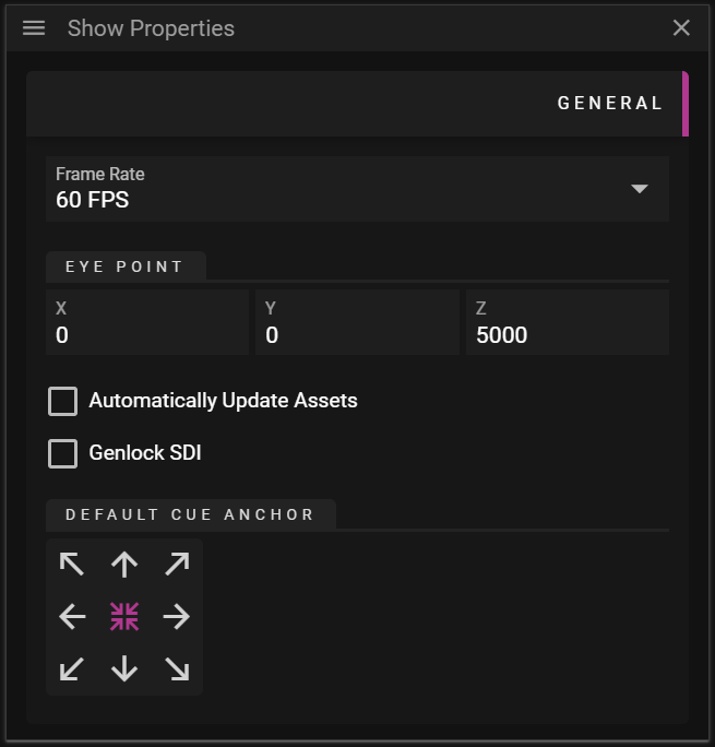
- Frame Rate defines the number of frames used per second during show playback.
- Eye Point defines the eye point, used to create the view frustum for all displays in the show.
- The eye point also affects the Default camera mode in Stage with the intent to make it WYSIWYG.
- Automatically Update Assets can be toggled on to have changes made to original asset files automatically update the assets used in the show.
- For instance, if you add a my_image.png to the show and then change the my_image.png in another program, you can have these changes trigger a new version of the asset being created.
- Genlock SDI can be toggled on to use a black burst signal to sync all the nodes used in the show. For this to work you need to connect a master signal source to the nodes that you want to sync.
- Default Cue Anchor defines the default anchor point for all new cues.
HARDWARE SYNC GROUPS
While WATCHOUT’s software-based synchronization across multiple nodes is generally sufficient, there are some cases when frame-accurate synchronization of display refresh cycles is required.
This section allows you to create hardware sync groups between machines for scenarios where exact sync between nodes is crucial.
Examples of hardware-assisted synchronization solutions include:
- NVIDIA Quadro G-Sync II, when used in conjunction with select NVIDIA Quadro graphics cards.
- ATI FirePro S400 Synchronization Module, when used in conjunction with select AMD FirePro graphics cards.
- WATCHPAX 60 (model C) with synchronized SDI outputs.
NOTE: When using AMD graphics, you need the synchronization module to accomplish frame accurate synchronization even within a single graphics card. This is generally not the case when used with NVIDIA graphics.
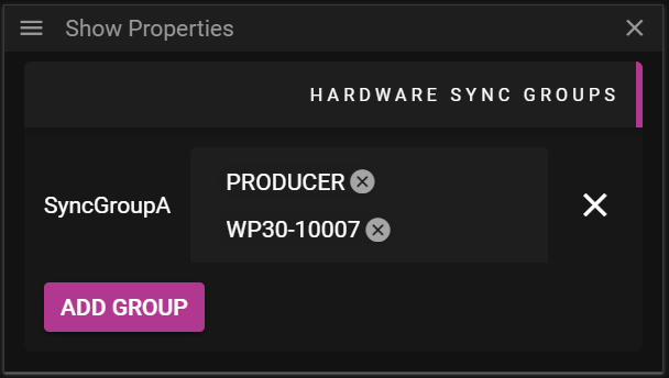
- Add Group can be clicked to create a new sync group.
- Once you have given a name to the sync group you can choose the nodes that you want to be part of the sync group.
- The nodes that are part of a hardware sync group require a special sync card to use this feature.
- You can use daisy chaining to sync multiple nodes with each other.
STAGE & DISPLAYS
In the world of WATCHOUT, Stage is a canvas and displays are windows onto that canvas.
- Each display server has a total pixel output of 8 x DCI 4k (8 x 4096 x 2160 pixels).
- A display server may utilize multiple GPUs to display content on multiple outputs.
By adding a display to Stage, you are effectively associating a physical output from a graphics card. It could for instance be a:
- Displayport output on a WATCHPAX 62S.
- SDI output on a WATCHPAX 62C.
- NDI output from a WATCHPAX 62B.
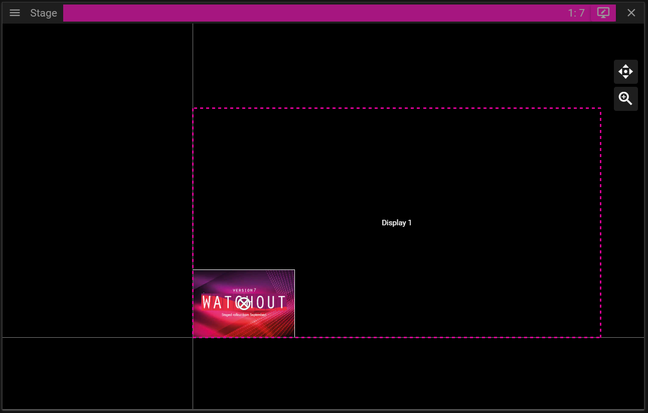
STAGE
The Stage window in Producer has two main purposes:
- Preview the show.
- Edit the show.
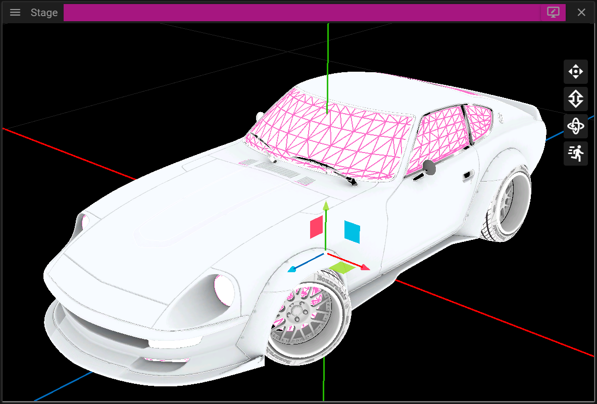
COORDINATE SYSTEM
Stage uses a right-handed coordinate system with a horizontal X-axis (red), a vertical Y-axis (green), and the Z-axis representing depth (blue). It is possible to visualize the coordinate system by holding your right hand in front of you. Hold your hand so that the thumb points to the right, your index finger points up and the middle finger points towards you. These three fingers then represent the x-, y- and z-axis where the:
- Thumb points along the positive x-axis.
- Index finger points the along positive y-axis.
- Middle finger points the along positive z-axis.
MENU
You can access the Stage menu from the top left corner of the window. It can also be found at the top menu bar of Producer under Stage.
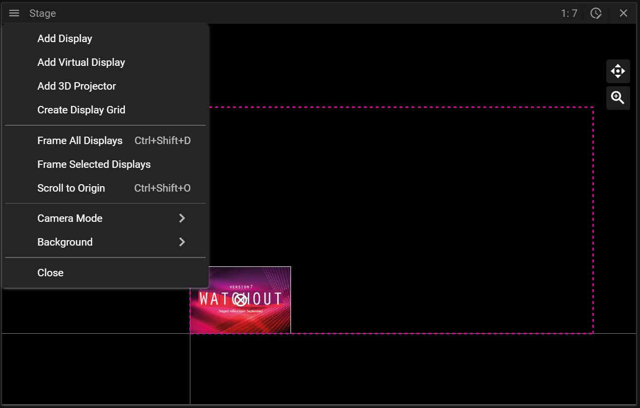
- Add Display creates a new display.
- Add Virtual Display creates a new virtual display.
- Add 3D Projector creates a new projector.
- Create Display Grid opens a dialog allowing you to add multiple displays in a single operation.
- Frame All Displays will change the scale of Stage so that all displays become visible.
- Note that this does only work in Default mode.
- Frame Selected Displays works like Frame All Displays but only by using the displays currently selected.
- Scroll to Origin resets the view to the default location.
- Camera Mode opens a sub menu allowing you to switch between different camera modes.
- Background allows you to change the background in Stage.
- Close the Stage window.
EDIT MODES
There are two edit modes in Stage:
- Display Edit Mode.
- Cue Edit Mode.
You can toggle between the edit modes by clicking the top bar in Stage. Notice that the color of the top bar changes depending on which edit mode you are in.
In display edit mode you can select and edit displays and in cue edit mode you can edit cues.
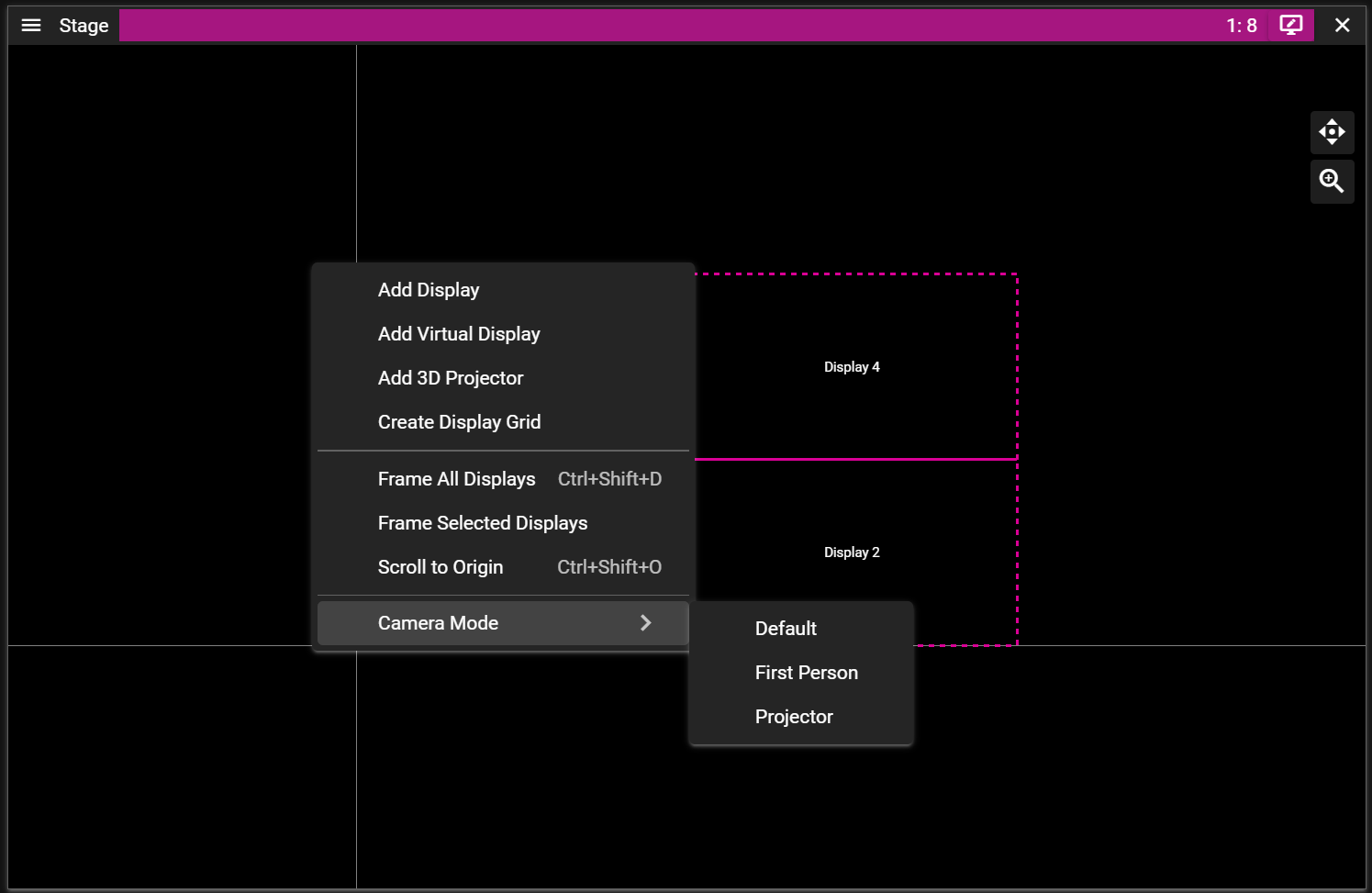
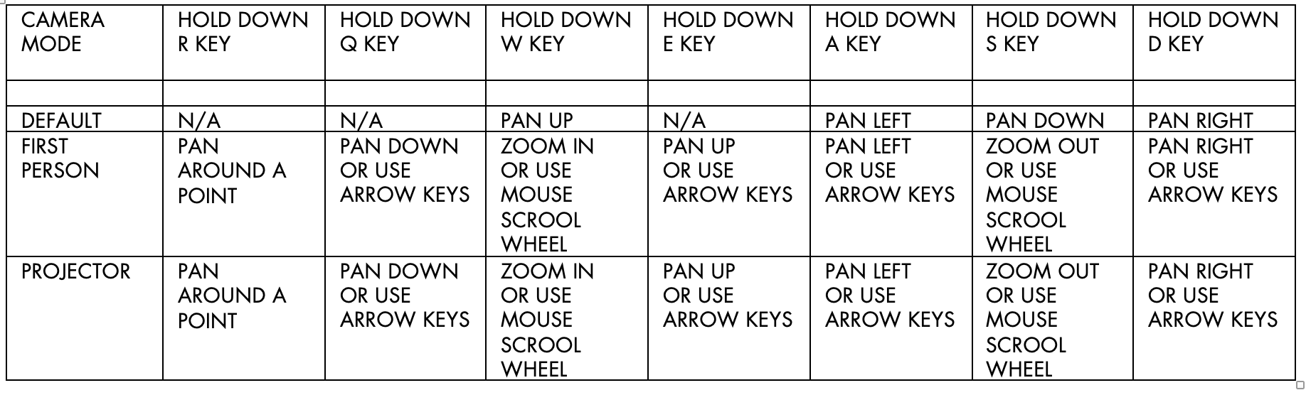
CAMERA MODE
Stage has three camera modes:
- Default.
- First Person.
- Projector.
Right-click in the Stage window to switch between these modes based on your needs.
DEFAULT CAMERA MODE
When starting WATCHOUT Producer, the Stage window will be in the Default camera mode. This mode is ideal for creating shows without 3D content, although it still supports 3D editing.
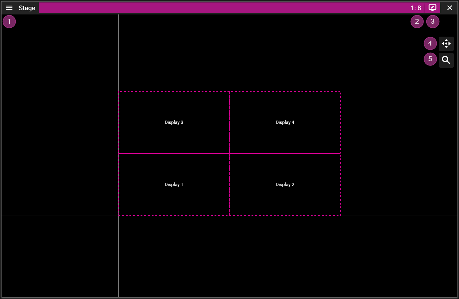
- Stage Menu.
- Stage Scale shows the active Stage scale.
- Use the mouse scroll wheel or the scale button to change the scale.
- Edit Mode can be switched by clicing on the top bar of the Stage window.
- Pan the view by clicking and dragging the pan button.
- Scale the view by clicking and dragging the scale button
- Note that you may also scale using the scroll wheel. This zoom operation will scale towards, or away from, where the mouse points.
FIRST PERSON CAMERA MODE
Designed for 3D tasks such as 3D mapping, the First Person camera mode offers greater navigation freedom compared to the Default mode.
This view uses a focus point, white sphere, to decide zoom target and what point to orbit around.
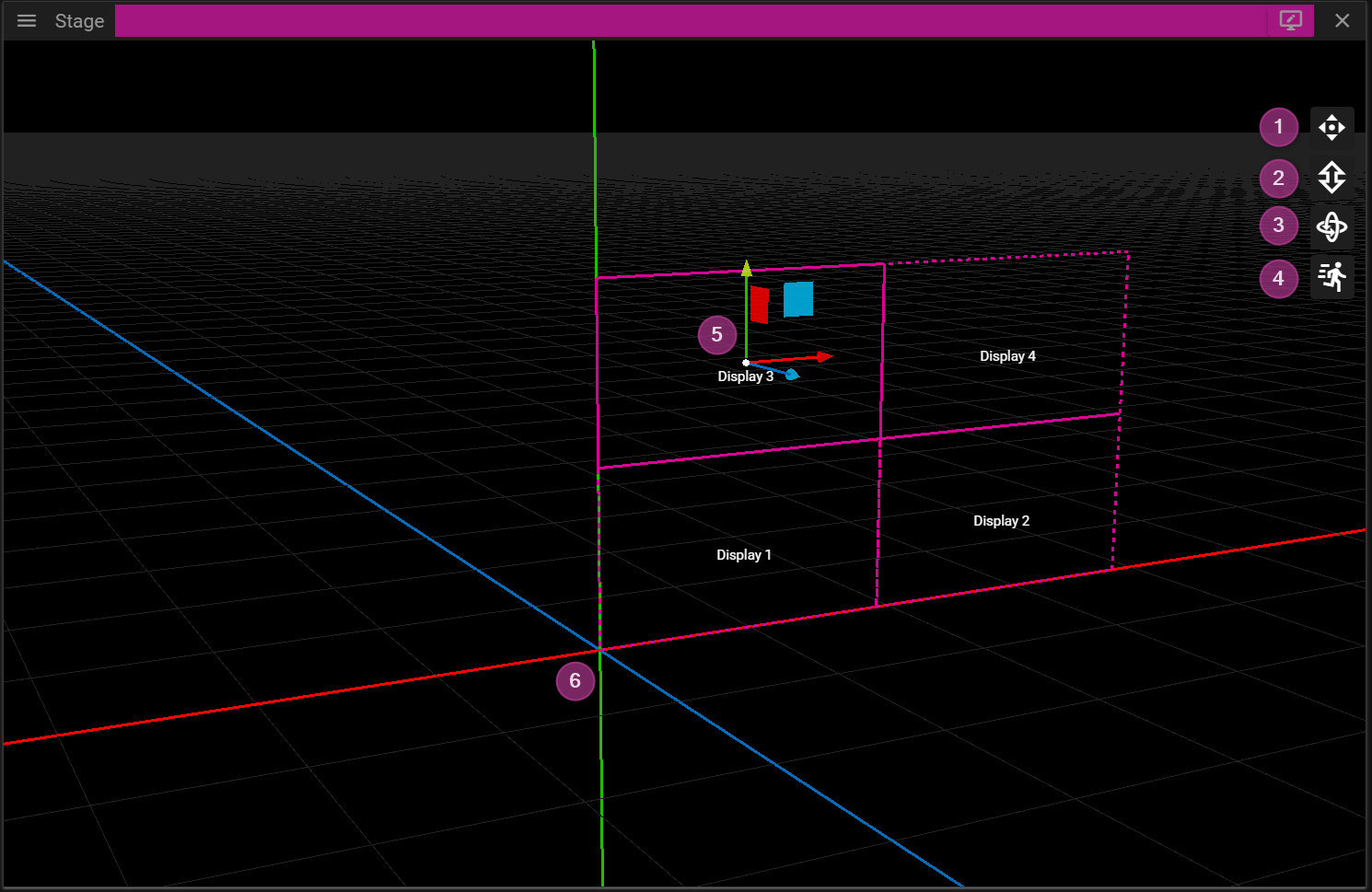
- Pan the view by clicking and dragging the pan button.
- Zoom the view by clicking and dragging the zoom button. The camera will zoom towards the focus point.
- Note that you may also zoom using the scroll wheel. This zoom operation will zoom towards (or away from) where the mouse points.
- Orbit the view around the focus point by clicking and dragging the orbit button.
- Velocity Control is used to adjust the camera movement velocity.
- Lowering the camera velocity is epspecially useful during 3D projector position fine tuning.
- Axis gizmo is used to move cues and displays in 3D. Click and drag drag an axis arrow (or a plane) to move objects.
- Notice that the positive direction of the axes are represented with arrows.
- Coordinate System origin with axes x (red), y (green) and z (blue).
PROJECTOR CAMERA MODE
In Projector camera mode, you view the virtual scene from the projector’s perspective. This is useful for projector positioning and calibration.
You may enter projector mode by either:
- Clicking on the Frame Display button (magnifying glass), in the Display Properties window.
or - By double-clicking a projector.
or - By right clicking in the Stage window.
The navigation in this mode mimics the navigation in the First Person mode with the exception that the scroll wheel zooms to target instead of zooming towards a focus point.
There is more information about the Projector mode in the 3D Mapping chapter.
MOVEMENT & SNAPPING
There are two ways to change the position of a display or cue:
- From the Properties window.
or - Inside the Stage window.
The Properties window will show a section named Position (or Position and Size) once a display or cue has been selected. Note that if you select multiple displays or cues you can edit them in a single operation.
To move a display, or cue, in the Stage window you need to click and drag it. Keep in mind that you may only select and move objects if you are in the correct Edit Mode.
If you hold the shift key you will get help lines that simplify movement along a specific axis.
During movement objects will try to snap to each other. The snapping can be toggled on/off from Edit/Snap found in the top menu bar of Producer.
You may tempoararily disable snapping by holding the ctrl key while moving an object.
STAGE TIERS
Stage Tiers are layers in the Stage window. They can be used to restrict media cues, on layers or on timelines. For example, if two overlapping displays are located on the same tier, in the Stage window, WATCHOUT will automatically create a soft edge blend between them. if you want to avoid the edge blend when two, or more, screens overlap in the Stage area, you would put them on different tiers.
KEYBOARD NAVIGATION
DISPLAYS
In this chapter you will learn about Stage displays and how these can be configured to control how and where the visual content of a show is rendered.
A Stage display is an object that resides in the Stage window. This object is then associated with a physical display device such as a projector, monitor, LED wall, video wall cube etc to make the show content visible for the audience.
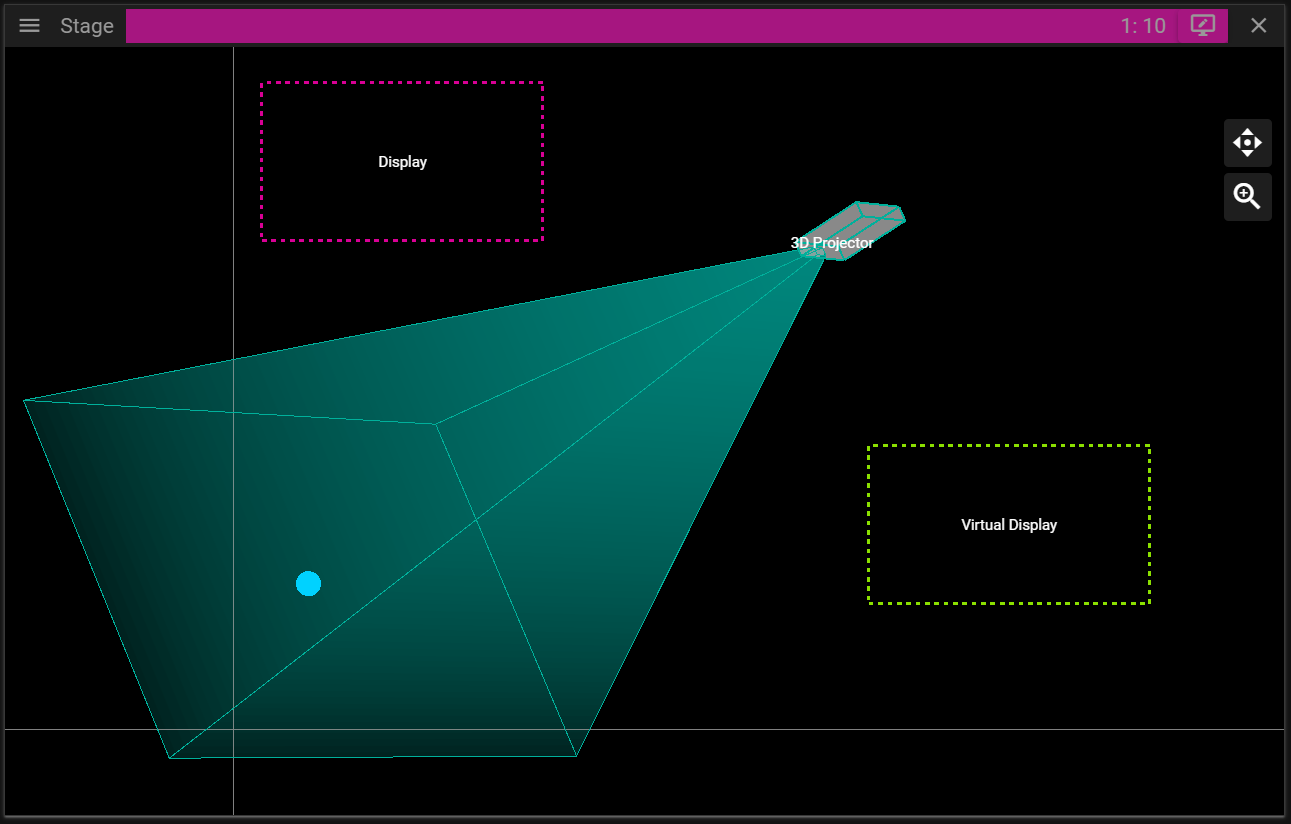
There are three different types of Stage displays in WATCHOUT:
- Display.
- Use this type to represent all flat display devices, as well as projectors when projecting onto a flat screen or a curved screen that can be managed by the Warp feature of WATCHOUT.
- 3D Projector.
- Use this type when projecting onto a complex, 3D object, represented by a 3D model in WATCHOUT. No automatic edge blending is applied, but manual masking can be used to manage overlapping areas.
- Virtual Display.
- Defines a rectangular area in Stage from which you can grab/record the resulting pixels for use as a new media item. This is useful when dealing with displays that have odd resolutions, such as LED wall modules (subsequently managed through an LED wall processor), or to create dynamic textures for mapping onto 3D models.
When a display is selected in the Devices window or in Stage, the Device Properties window becomes active.
You can learn more about adding displays and projectors in the Stage chapter.
DISPLAY PROPERTIES
In this chapter you will learn about the display properties that can be configured.
GENERAL
This property group contains:
- Device Name can be set to anything you like. This name is shown in the Stage window when you are in Display Edit Mode.
- Device Host is used to set the node on which the display content will be rendered.
- Heart button is used to toggle the activate or deactivate the display.
- Lock button is used to toggle the possibility to edit the display.
- Frame button is used to change the scale in Stage so the selected display(s) are in focus.
- Color button is used to change the frame color of the display. Use it to make it easier to find specific displays.
- The color is also shown in the Devices Window.
In order to see any output from a display on a monitor etc you need to enable it. To enable a display you need to:
- Select the display.
- Make sure you are in Display Edit Mode otherwise you cannot select displays.
- Assign it to a node by setting the Device Host.
- Locate and click the heart icon located in the General section.
PLACEMENT
This property group contains:
- Initial Position can be changed to edit the position of the display.
- Initial Rotation can be changed to rotate the display counter clockwise around the anchor point.
- Anchor defines the origin of the display and it also defines the point around which the display is rotated.
- The anchor widget, with arrows, can be used to move the anchor point to a specific corner, edge or the center of the display.
- Projector specific settings:
- Eye defines the point where the projector is located.
- Target defines the target point of the projector when there is no lense shifting.
- Lense Shift can be used to change where the projector displays its image without changing the position of the projector.
- Width / Distance Ratio can be used to change the shape of the projection frustum.
- Note: During the calibration step when doing 3D Mapping a number of the projector settings above are modified.
In the following example the anchor and rotation of a display is being edited:
PRESENTATION
This property group contains:
- Tiers
- Show Cues on Stage Tiers can be changed to make the display only render cues that belong to a specific tier.
OUTPUT
This property group contains:
- Route
- Device defines the target buffer for the display. It can be set to GPU, SDI, NDI® and Virtual.
- Channel defines the display device to render the display content to.
- Dimensions
- Resolution is used to define the wanted output resolution. That is the resolution of the buffer to which WATCHOUT renders the cues.
- Use as Input Resolution can be toggled off to use a custom resolution for the display in Stage.
- Signal
- Color Depth defines the number bits used per color channel/component.
- Color Space defines the color space to use for rendering.
- Delay
- Delay frames allows you to delay the rendering of a display. This can be useful to make different displays play exactly in sync.
WARP
Warping can be useful to make the display output follow an irregular surface, like a curved wall. This property group contains:
- Edit Warp button opens a window allowing you to modify the warp mesh onto which cues are rendered.
- Enable Warp toggles warping on or off.
- Show Warp Points on Display toggles the rendering of warp points on or off.
NOTE: You can use a XBox type of controller to adjust the warp points.
For more information look in Appendices / XBox Controller
Below we edit the warp mesh to change how the output is rendered:
Before:
After:
MASK
Masking can be useful in situations where you want to block parts of the display output. For instance, if you have a pillar between a projector and the projection surface you might want to avoid displaying content on the pillar. This can be achieved by using mask(s).
This property group contains:
- Edit Mask button that opens a window allowing you to add masks to hide pixels from being rendered to specific parts of an output.
- Automatic Soft Edges checkbox to activate blending in the areas where displays overlap.
CALIBRATION
Set a NDI® Calibration Stream for the auto calibration system to take over the display. The name of the NDI® stream is given by the auto calibration software.
Assume we want to calibrate two projectors so they produce a continuous image. An auto calibration software then produces a test pattern that is outputted by the two projectors and analyzed by a camera. The auto calibration then makes the necessary changes to align the two projectors so they form a continuous image.
WHITE POINT
The white point allows you to define what color in the output should be considered as white.
TEST PATTERN
This property group contains the possibility to change the output of the display to a specific pattern. This can for instance be useful when working with multiple overlapping display devices. The patterns at hand are:
- None, outputs the cues associated with the display.
- Muted, outputs nothing for the display even if it is active.
- White, outputs white color.
- Masked, outputs the masks if any.
- Pattern, outputs a checker pattern.
You can also toggle Render Info on and off. This information can be helpful to identify screens if there are many outputs.
VIRTUAL DISPLAYS
Just like an ordinary Stage display a virtual display is defined by a rectangular area in which cues can be placed. However, instead of outputting the rendered cues directly to a physical display device, like a monitor, the virtual display renders the cues to a buffer. This buffer can then be used just like a media asset that can be rendered to an ordinary display or projector.
You can think of this process as the virtual display is recording content and creating a media asset on the fly. The media asset can then be used as a regular cue or as a texture for a 3D model.
The short clip below shows the following sequence:
- Create a virtual display.
- Drag the virtual display from the Devices window to the timeline. This creates a cue using what the virtual display is capturing as a media.
- Change the position of the virtual display, showcasing that it changes how it records the regular media cue.
- Add a 3D model and apply the virtual display to it which means the recorded content will be used as texture.
- Change the position of the virtual display, again showcasing how the virtual display output content changes.
ASSETS & ASSET MANAGER
Earlier versions of WATCHOUT featured the Media window, which listed available content in your show. In WATCHOUT 7, this is now the Assets window. Media files are not loaded into the WATCHOUT show file but are stored in the Asset Manager.
ASSET MANAGER
You can think of an asset as a piece of data stored in a file, like image or audio data. The assets used to build a show in WATCHOUT are handled by the Asset Manager. The purpose of the Asset Manager is to:
- Prepare assets for being used in WATCHOUT shows.
- Organize assets.
- Share assets between projects and users.
The Asset Manager does not need to be located on the machine running Producer, it can be on any node available on your network. Since preparing assets can be a time consuming and CPU and GPU intensive task, it can be beneficial to share a powerful machine among creators.
Note that you may organize your assets into folders just like any other file system.
In order to make use of assets they need to be added to the show. This is done by either dropping them to a Timeline or to the Stage window which creates a cue that can be used to configure how the data stored in asset is visualized/played.
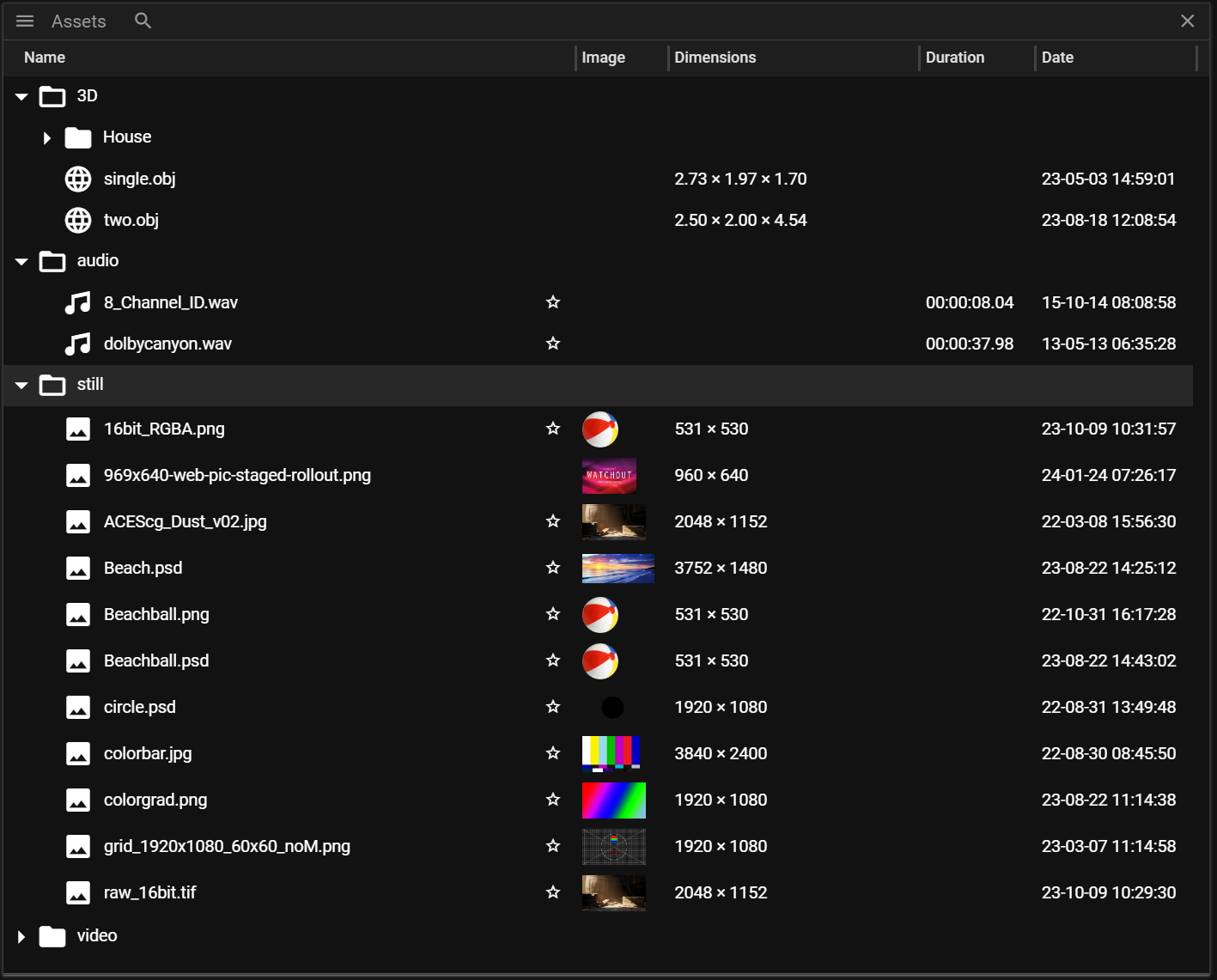
- Magnifying glass icon is used to open the search interface.
- Name will show the name of the asset. This can be edited in the Asset Properties.
- Image will show a thumbnail of the asset.
- Note that not all assets have a thumbnail.
- Dimensions shows the resolution for media and the size for 3D models.
- Note that not all assets have a dimension.
- Duration shows the duration of the asset (available for videos and audio)
- Date shows when the original file was created (this does not show when the asset was added to Producer).
ASSET TYPES
WATCHOUT supports the following asset types:
- Image (.webp, .tiff, .jpg, .png, .psd, .gif, .tga)
- Video (.mp4, .mov)
- h262, h264, h265, ProRes, NotchLC, Hap.
- Audio (.wav, .mp3, .mp4, .ogg, etc)
- 3D Model (.obj, .gltf, .glb, .3ds)
- Mpcdi (.mpcdi)
- Display settings file format.
- Composition
- A group of assets bundled together.
ASSET MANAGER MENU
The Asset Manager menu looks like this:
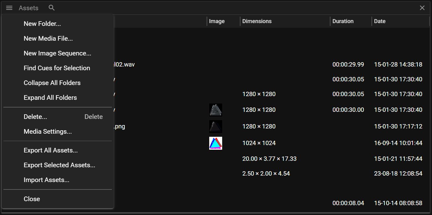
- New Folder will open a dialog where you can set the name of the folder you want to create.
- New Media File will open a dialog allowing you to add an asset.
- New Image Sequence will open a dialog allowing you to add a sequence (.tiff or .tga).
- Find Cues for Selection will search for cues referring to the selected assets. More information can be found here.
- Collapse all Folders will collapse all open folders.
- Expand all Folders will expand all closed folders.
- Delete will delete the selected assets.
- Media Settings will open a dialog allowing you to define how different formats are converted during WATHOUT asset preparation.
- Export All Assets will open a dialog allowing you bundle all assets in the Asset Manager to a package.
- Export Selected Assets will open a dialog allowing you bundle the selected assets in the Asset Manager to a package.
- Import Asset will import assets that were previously exported.
ADDING ASSETS
To add an asset to the Asset Manager you can either:
- Go to the menu and select New Media File (or New Image Sequence).
OR - Drag and drop a file from your file system to the Asset Manager.
Once the asset has been added the Asset Manager will begin to prepare the asset for being used in WATCHOUT shows. This will also produce a star that is there to convey that this is a new asset.
SELECTING ASSETS
You select an asset by clicking on it. Producer also supports holding the Control/Shift-key to alter the select operation. You can also use Control+A to select all assets in the Asset Manager.
When an asset is selected the Properties window is populated with asset information - Asset Properties.
REMOVING ASSETS
Select an asset(s) in the list and click the Delete key or select Delete in the Asset Manager menu.
FOLDERS
Producer supports importing complete folder structures which is very useful if you already organized your assets in a specific way. If you want to add a folder structure to the Asset Manager you simply drag and drop it in the Asset Manager window.
You can also create (or delete) new folders from the Asset Manager menu. If you want to move an asset to a specific folder you select and drag it to the folder you want it to reside in.
SEARCH
Click on the magnifying glass icon at the top of the Asset Manager to open the asset search interface.
To search for an asset you input text in the search field. You can further narrow down the search result by:
- Filter out a specific asset type by changing the asset type drop down.
- Filter out newly created assets (assets marked with a star).
- Filter out assets based on what cues you currently have selected on your Timeline(s).
Hide the search functionality by clicking on the cross at the far right.
FIND CUES FROM ASSETS
Sometimes it might be helpful to find cues that are using a specific asset. To do this you need to:
- Select the asset(s) of interest.
- Right-click in the Asset Manager window and select Find Cues for Selection.
- The search result is shown in the bottom part of the Asset Manager window.
The search result is interactive so you can click on the cue you want to inspect. Doing so will activate the Timeline that owns the cue and scroll to it. You can also use the down/up button to jump to next/previous in the result. Next to these buttons is a select all cues button which is useful if you want to delete all cues referring to a specific asset. Note that you can use the arrow down/up to to jump to next/previous the result.
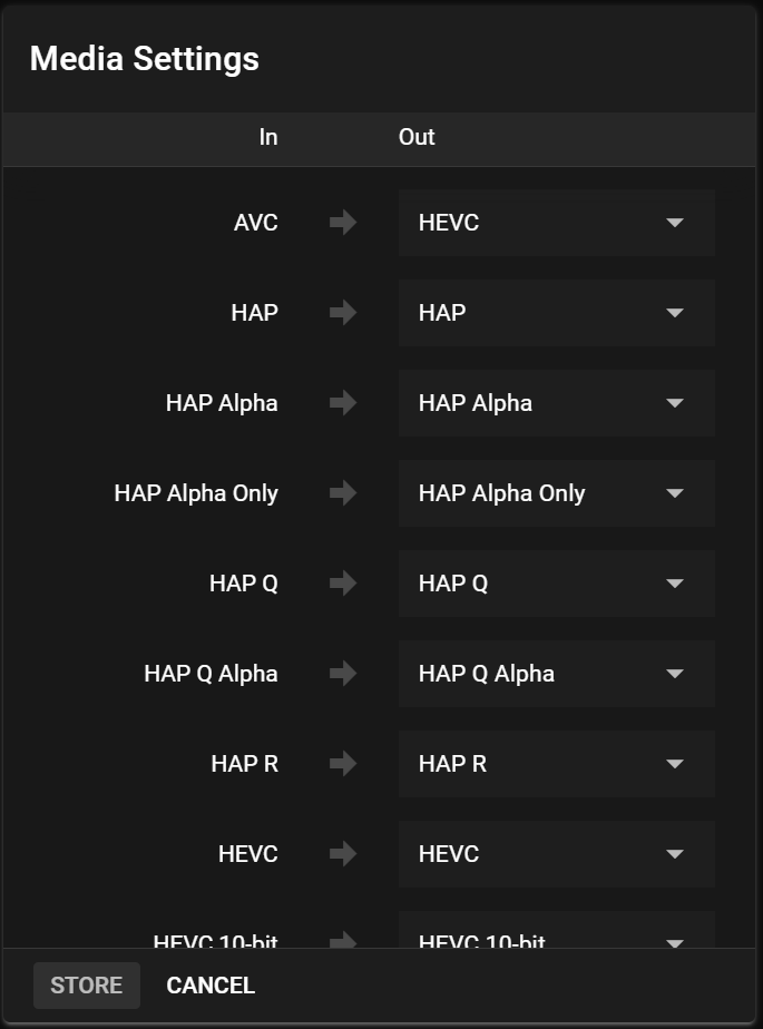
MEDIA SETTINGS
The Media Settings can be accessed from the Asset Manager menu and it will open a dialog allowing you to define how different formats are converted during WATHOUT asset preparation. This is done by changing the Out format.
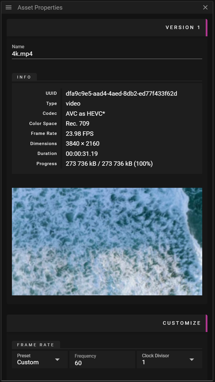
ASSET PROPERTIES
The Asset Properties window provides information about the selected asset(s) along with a few possibilities to edit the asset(s).
VERSION NR
An asset can have multiple versions and at the top of this the Asset Properties you can see the version number section. New versions of an asset can be created by modifying them in the Customize section of the asset properties or by dropping a new asset in the Asset Properties window. A cue can then decide if it wants to use the latest available version of an asset or if it like to use a specific version of an asset.
The Name field will show the original name of the asset but note that you may edit this name.
Below is information about the asset. The information will vary depending on the selected asset(s) and their type(s). The information section cannot be edited.
- All asset types:
- UUID is a universal unique identifier for the asset. When a new asset is added, or a new version of an asset is added, a new UUID is created.
- Note that you will create two different UUID even if you load the same asset twice.
- Type contains information about the asset type.
- Progress is updated while an asset is being prepared for WATCHOUT.
- It will display "processed size"/"estimated final size" "(progress in percentage)".
- Note that once the asset preparation is done the "estimated final size" will show the actual size on the disc.
- UUID is a universal unique identifier for the asset. When a new asset is added, or a new version of an asset is added, a new UUID is created.
- Video:
- Frame Rate contains the number of frames played per second.
- Video/Image:
- Color Space shows the color space used during playback.
- Dimensions shows the resolution of the asset if
- Codec contains information of what format is used to store the data.
- Note that it shows information in the form original -> WATCHOUT playback format.
- Video/Audio:
- Duration shows the duration of the asset.
- Audio:
- Channels shows the number of channels available in the audio.
- Sample Rate shows the sample rate for the audio.
- Model:
- Dimensions shows the size of the original model in the unit that was used when the model was created.
CUSTOMIZE
In this section you may customize assets.
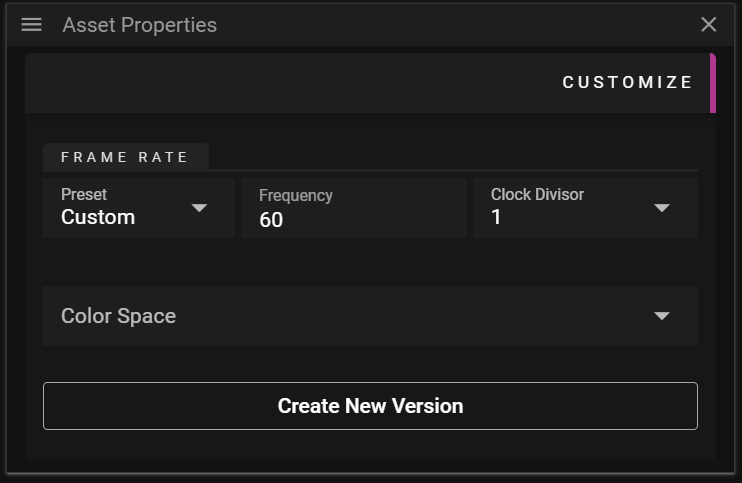
- Video
- Frame rate
- Color Space
- Image
- Color Space
- Audio
- Sample Rate
To create a new version make the wanted adjustments and click Create New Version. Note that if a cue refers to this asset and has its version set to Latest the cue will automatically use the newly created version.
TIMELINES & CUES
In this chapter you will learn about what a Timeline is and how you can use cues to populate your Timeline(s) with content.

TIMELINE
A Timeline is where you place the content that you want to play to your audience. The content, like videos or audio, is defined in assets and by dragging an asset to a Layer on the Timeline you create cue. By selecting a cue on the timeline you can further edit how the referred asset is used in the show. For instance, you may want to change the duration of a video clip or you may want to add an Effect.

- Name shows the name of the Timeline.
- Time Position Indicator shows the current time position using a vertical line drawn through the Timeline window.
- Its color indicates the Click Jumps to Time state.
- Jump button to jump to where the Time Position Indicator is located on the Timeline.
- Timeline Time shows where the Time Position Indicator is located.
- Edit this to jump to a specific time.
- Active Layer shows a pink vertical bar to convey that this layer is active.
- Cue object that can be selected to edit show content.
- Effects shows the chosen effects for the selected cue.
- Use the eye to hide/show a specific effect curve
- Tween Curve allows you to create and edit tween points.
- Play button to start the playback.
- Pause button to pause the playback.
- Stop button to stop the playback.
- Zoom Out button to zoom out the Timeline view.
- Zoom In button to zoom in the Timeline view.
- Horizontal Scrollbar to scroll to a specific time in the Timeline view.
TIMELINE CONTEXT MENU
There are two context menus in the Timeline window, one for editing the timeline itself and one for working with cues.
TIMELINE GENERAL CONTEXT MENU
If you right-click in the Timeline window, without having any cue selected, you will open the general context menu.
You can also open this menu by clicking on the three horizontal lines in the top left corner of the Timeline window.

- Cue operations:
- Add Play Control Cue adds a play control cue.
- Add Pause Control Cue adds a pause control cue.
- Add Output Cue adds an output control cue.
- Add Marker Cue adds a marker cue.
- Layer operations:
- Insert Layer inserts a layer above the active layer.
- Add Layer adds an additional layer at the top of the Timeline.
- Delete Layer deletes an additional layer at the top of the Timeline.
- Select All Layer Cues selects all cues on the active layer.
TIMELINE CUE CONTEXT MENU
If you right-click in the Timeline window, while having one or multiple cues selected, you will open the cue context menu.
You can also open this menu by clicking on the three horizontal lines in the top left corner of the Timeline window. Again, at least one cue needs to be selected for this menu to be shown.

- Properties activate and show the Cue Properties window.
- Find Asset tries to find the asset(s) associated with the selected cue(s).
- The asset(s) found will be selected in the Asset Manager window.
- Move opens a dialog that allows you to move the selected cue(s).
- Cut cuts the selected cue(s) allowing you to paste the cue(s) later on.
- Copy copies the selected cue(s) allowing you to paste the cue(s) later on.
- Delete deletes the selected cue(s).
- Effect opens a sub menu allowing you to add or remove effects to the selected cue(s). .
- Trim allows you to shorten the duration of the selected cue(s) based on where the Time Position Indicator is located.
- Start edit the start time of the cue.
- End edit the end time of the cue.
- Reset allows you to reset some settings.
- In-Time.
- Duration resets the duration of the selected cue(s) to the original duration.
LAYERS
A Timeline consists of multiple layers on which cues can be added. When the show is empty you can think of the layers in the Timeline as a stack of fully transparent papers. As you add image or video cues to the layers you will fill these transparent "papers" with pixels. The layer with the highest number represents the top of the "paper" stack which means that cues placed on this layer will render on top of cues placed on layers below it. You may override this behaviour by changing the Stacking on the cue.
Layers further up the layer stack may occlude cues further down:

If a cue is selected on the timeline it will be prioritized for movement operations in the Stage window:

CUE OVERLAPS
When two cues reside on the same layer they may overlap. This is usually an unwanted state so when an overlap has been detected the affected cue objects, in the Timeline, are marked with a striped pattern. This can be resolved by selecting and moving cues until the pattern disappears.
Not all cue overlaps are forbidden. Media cues may have overlapping cues of the following types:

There is also another exception where cue overlaps are allowed and that is when you are using Fade-in/out as shown in the video below:

TIME POSITION INDICATOR
The Timeline Position Indicator shows the current time position using a vertical line drawn through the Timeline window. Its color indicates if the Click Jumps to Time is active. If it is active it means that when a cue is selected the Timeline Position Indicator will jump to the start of the cue.
The Timeline Position Indicator is drawn as a solid pink line if Click Jumps to Time is active, otherwise it will be drawn as a dashed purple line.

CUE TRIM
This feature allows you to change the duration and starting/end frame of the referred asset based on where the Time Position Indicator is located. You can think of it as cutting out parts of the start or the end of a video or audio clip. When you trim a cue using Start the In-time property is changed.

TIMELINE PROPERTIES
In this chapter you will learn about the available Timeline Properties.
GENERAL

- Name defines the name of the Timeline.
- Duration defines the duration of the Timeline.
- This input field supports using a letter to define the unit of the inputed value:
- s/seconds for seconds.
- m/minutes for minutes.
- h/hours for hours.
- This input field supports using a letter to define the unit of the inputed value:
- Stacking defines the render order of content from different timelines.
- Timeline Order uses the order in which the Timelines are listed in the Timelines window window.
- Always on Top means that the content of this Timeline will render on top of other Timeline(s).
- Clarification: Always on Top is always rendered on top of Timelines using the Timeline Order. If multiple Timelines are using Always on Top the order in which Always on Top was activated will decide the render order. The Timeline that activated Always on Top most recently will be the topmost Timeline.
- Auto Run can be activated to make the timeline start playing automatically once the Director has loaded the show.
TRIGGERS

- Play Expression defines an expression that can trigger play.
- Pause Expression defines an expression that can trigger pause
- Stop Expression defines an expression that can trigger stop
You can read more about expressions here.
FAQ
Q. Which Timeline is rendered on top if multiple Timeline(s) uses Always on Top?
A. If multiple Timelines uses Always on Top the order in which Always on Top was activated for the Timeline will decide the render order.
-
For instance, let us assume you have three Timeline(s) called A, B and C, each with Stacking set to Timeline Order.
- You set Always on Top for A.
- This means that A will render on top of B and C. The render order for B and C is still decided by the Timeline Order.
- Later on you set Always on Top for B.
- This means that B will now render on top of A (since it was changed after A).
- Note that A will still render before C since Always on Top is always rendered on top of Timeline(s) using the Timeline Order.
- You set Always on Top for A.
TIMELINES
Producer supports having multiple timelines. These timelines are organized in the Timelines window.
Using multiple timelines can be useful in a number of situations, for instance if you want to play specific content on demand.

- Name shows the name of the timeline.
- Status shows whether the timeline is played, paused or stopped.
- Time shows the time the timeline is currently at.
- Play Expression expression that trigger play.
- Pause Expression expression that trigger pause.
- Stop Expression expression that trigger stop.

TIMELINES CONTEXT MENU
You can access the Timelines context menu by right-clicking in the Timelines window. You can also open this menu from by clicking on the three horizontal lines in the top left corner of the Timelines window.

- Add Timeline adds a new timeline.
- Add Folder adds a new folder.
- Delete deletes the selected Timeline(s).
- Properties activates and shows the Timeline Properties window.
FAQ
Q. What is the benefit from using multiple timelines? Why cannot I just add another layer?
A. Multiple timelines give you the possibility to organize your show into smaller chunks with descriptive names. It also allows you better control over when specific content should be played.
CUE
A cue is an object that exists on a layer in a Timeline. To create a cue you simply drag an asset from the Asset Manager to a layer on the Timeline. This will create a placeholder for the asset, the cue, that can be used to edit how the content of the asset is being used in a WATCHOUT show.

WATCHOUT supports the following cue types:
When a cue is selected on the Timeline or in Stage, the Cue Properties window becomes active.
If the Time Position Indicator overlaps the cue, and the cue refers to something visual, it will be shown in the Stage window.

CUE TYPES
In this section we cover the cue types you can use to build WATCHOUT shows.
MEDIA CUES
A cue that produces pixels or audio is referred to as a media cue. The word media cues are used in the documentation to explain concepts that are common for these cues.
The following cues are considered to be media cues:
IMAGE CUE
A cue that refers to an image asset like a .png or .psd file.
VIDEO CUE
A cue that refers to a video asset like a .mp4 or .mov file.
AUDIO CUE
A cue that refers to an audio asset like a .wav file.
3D MODEL CUE
A cue that refers to a 3D model asset like a .obj file.
You can read more about 3D models here.
VIRTUAL DISPLAY CUE
A cue that is used to display content recorded by a virtual display. Virtual display cues are created by:
- Right-click the Stage window and select Add Virtual Display.
- Drag the virtual display from the Devices window to a Timeline.
- Note that you can replay the recorded content on the surface of a 3D model. To do so you need to drop the virtual display on top of a cue referring to a 3D model/mesh.
Virtual display rendering does not come for free. To record content so it can be replayed the content must be rendered to an offscreen buffer on the GPU. This implies both more memory consumption and more rendering overhead. Needless to say you should use virtual displays with care to avoid severe performance penalties.
This cue supports the same properties as an image cue.
You can learn more about virtual displays here.
CAPTURE CUE
A cue that can be used to display data captured by a Capture Device. This cue supports the same properties as an image cue.
COMPOSITION CUE
A cue that consists of a group of cues defined on a Composition Timeline.
A composition cue makes it easy to re-use or re-arrange show sections or short snippets. It also makes it easier to apply the same effect to a group of media elements – for instance, to move and scale a set of images together.
There are two ways to create composition cues:
-
Primary approach:
-
- Selecting cues you want to group into a composition.
-
- Select Group Cues into Composition in the Producer/Timeline menu.
- Note that you may also explode a group into separate cues. This is done by selecting Ungroup Cues from the Producer/Timeline menu.
OR
-
-
3D model approach:
- Drop a 3D model asset containing multiple meshes to a Timeline or the Stage window.
- Each mesh is represented as a cue on a separate layer which gives the possibility to play different media (and effects) on each mesh.
To access the composition Timeline you can double click on the composition cue. Note that this will have Stage only show what is present in the composition timeline, everything else is hidden.
Changes made to a composition, such as swapping a media cue, will automatically be applied across all instances of that composition on all timelines.
VARIABLE CUE
A cue that refers to a variable defined in the Variables window. Create this cue by dragging a variable from the Variables window to the timeline.
Select the cue to and edit the Effect to configure how variable value changes over time.
CONTROL CUE
A cue that can be used to trigger jumps in time and change playback state for one or multiple Timelines.
OUTPUT CUE
A cue that gives you the possibility to send arbitrary data to a device on the network. The data is sent when the Timeline time reaches the cue Start Time.
You can read more about its properties here.
MARKER CUE
A cue that can be used to simplify WATCHOUT show monitoring and control. It gives the user the possibility to define a description and count down/up labels.
CUE PROPERTIES
In this chapter you will learn about the available Cue Properties.
GENERAL
The General section allows you to edit common data such as Start Time and Duration.

- Start Time defines when the cue starts playing.
- Color defines the color used for the cue on the Timeline.
- The main purpose is to make it easier to organize the cues used in your show.
- Lock can be activated to disable the possibility to edit a cue.
- Media cue specific settings:
- Duration defines how long the cue will be playing.
- Pre-roll defines how far ahead the cue Start Time the referred media asset is prepared by the media server (loaded from the disc etc).
- Control and marker cue specific settings:
- Name a user defined name for the cue. For instance useful when defining jumps in time.
PLACEMENT
The Placement section allows you to edit data related to the location of the cue in the Stage window.

- Initial Position defines the position of the cue without any effects applied to it.
- Initial Rotation defines the rotation of the cue without any effects applied to it.
- Anchor Point defines a cue local point that does not move when scaling and rotating the cue.
- The anchor widget, with arrows, can be used to move the anchor point to the corners, edges or the center of the cue.
MEDIA PLAYBACK
The Media Playback section allows you to edit data related looping and time offset for the referred asset.

- Free Running activates the play state of the cue regardless of the Timeline play state.
- Looping activates looping of the referred asset.
- Start Point defines from what time in the referred asset the looping will start.
- End Point defines from what time in the referred asset the looping will end.
- In-time defines the offset where the cue will start playing the asset it refers to.
- For instance, if you want to skip playing the first second of a video you can set this to one second.
Free running and looping changes the appearance of the cue:
- Free Running

- Looping

FADE IN/OUT
The Fade-in/out section allows you to edit how the referred asset gradually becomes visible (fade-in), from when the play state reaches the of the cue, and how it gradually becomes invisible (fade-out) until the play state reaches the end of the cue.

- Enable Fade-in adds a fade-in effect
- Enable Fade-out adds a fade-out effect
- Curve defines what curve to use for the effect.
- Duration defines the duration of the effect.
PRESENTATION
The Asset section allows you to edit data related to rendering of the referred asset.

- Frame Blending activates smooth transitions between media frames.
- Note that it consumes more memory.
- HW Acceleration is used for decoding specific codecs, like HEVC.
- Depending on your system and scenario it may be more efficient to keep this deactivated.
- Blend Mode defines how cues using transparency are blended against what has already been rendered.
- Available options are Add, Multiply, Screen, Lighten, Darken and Linear Burn.
- Render Surface defines if you are to render the Inside, Outside or Both Sides of the cue surface.
- For instance this can be useful to handle 3D models that have inconsistencies related to the front and back side of its polygons.
- Stacking defines the order in which cues on the Timeline are rendered.
- By Layer means that the layer number defines the render order.
- Layer N is rendered before layer N + 1.
- By Z means that the cue surface depth, the distance to the camera, defines the render order.
- By Layer means that the layer number defines the render order.
- Show on Stage Tiers defines the tiers in which the cue will be rendered.
- A display may decide to only render cues belonging to a specific tier.
ASSET
The Asset section allows you to edit data related to the referred asset.

- Asset Version defines the version to use for the referred asset.
- Latest means the cue will use the latest available version of the asset.
- If a new version of the asset is created the cue will use the new asset version.
- Fixed means that a fixed version for the referred asset is used.
- Latest means the cue will use the latest available version of the asset.
- SDR White Point defines the standard-dynamic-range white point in nits.
MARKER
The Marker section allows you to edit data related marker cues.

- Description contains an optional user defined text.
- Count Down activates a count down label on the Timeline cue object.
- Count Up activates a count up label on the Timeline cue object.
- Duration is used to control the time period in which the count down/up label is visible.
OUTPUT
The Output section allows you to edit data related output cues. An output gives you the possibility to send arbitrary data to a device on the network. The data is sent when the Timeline time reaches the cue Start Time.

- Protocol defines the protocol to use for the data being sent.
- TCP protocol.
- UDP protocol.
- Address defines the address of the device that should receive the data.
- Data to Send defines the data, in text, that should be sent.
PLAYBACK CONTROL
The Playback Control section allows you to edit data related control cues. A control cue can be used to edit the time and state of one or multiple Timelines.

- Target Timelines defines which Timeline(s) that are affected by the Timeline Actions.
- All makes the Timeline Actions affect all Timelines.
- Others makes the Timeline Actions affect all but the Timeline in which the control cues exist.
- List makes the Timeline Actions affect all Timelines checked in the Include drop-down.
- Timeline Actions:
- Jump defines if the player should make a jump when the show reaches the cue.
- No Jump
- To Time
- To Cue
- Target Cue defines a cue Name to jump to.
- First searches for the closest cue residing after the control cue. If no match is found it then searches for cues residing before the control cue.
- Backwards to Cue defines a cue Name to jump backwards to.
- Only searches for cues residing before the control cue.
- Set Timeline State defines the state of the timeline when the show reaches the cue.
- Play
- Pause
- Stop
- Jump defines if the player should make a jump when the show reaches the cue.
CHANNEL MAPPING
The Channel section allows you to edit data related audio cues.

- Input Channels defines the channels read from the audio source.
- Buses defines where the Input Channels are routed
- Plus can be clicked to extend the channel matrix.
There is more in-depth information on how to configure the Channel Mapping matrix in the following chapter.
SIZE
The Size section allows you to edit data related to the size of a 3D model.
Imported 3D models are automatically scaled to fit a 1000 x 1000 x 1000 pixel cube.

- Scale defines what method to use for setting the size.
- To Size allows you to control the maximum extent (width, height or depth) of a 3D model.
- By Factor allows you to set a uniform scale factor of the model.
- If you set this value to 1.0 you will get the original size of the 3D model.
If you want to perform non-uniform scaling you need to edit your 3D model outside Producer.
There is more information about 3D models here.
SURFACE
The Surface section allows you to edit data related to the surface of a 3D model.

- Name shows the name of the mesh.
- Asset shows the name of the asset file being referred.
- Remove Texture allows you to remove media that has been applied to the mesh surface.
There is more information about 3D models here.
FAQ
Q. How does Looping work with In-time?
A. If you have set In-time to non-zero only the first iteration of the looping will have the initial frames trimmed (according to the In-time). Later iterations will use the full length of the asset.
Q. I have locked a cue. Can this cue be updated in any way?
A. Yes. If the cue is using *Latest for the Asset Version it will still be updated if an asset is updated with a new version.
EFFECTS
In WATCHOUT 7, Effects (called tweens in previous versions) are applied to media Cues. An Effect is a real-time change to a media Cue when it is played back.
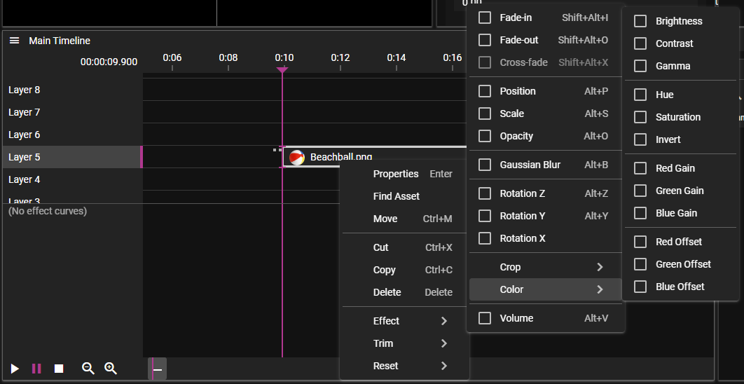
EFFECT MENU
Effects can be toggled on a media Cue by selecting it in the Timeline and using the Effect menu, or right clicking the Cue, and accessing the Effect menu that way.
EFFECT VIEW
Effects are shown in a single unified view, with a list of the different Effects assigned to the currently selected Cue, to the left (1). This list contains the name of the Effect, it's current value, together with a button (2) to toggle visibility of the Effect in the curve view.
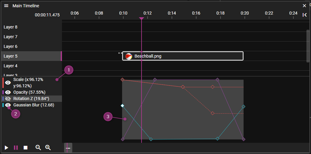
In the Effect curve view (3) you can edit the Effect curves by adding, moving, and in other ways, editing Tween Points.
EFFECT PROPERTIES
In the Properties window for Effects you can generally edit the Expression for this Effect. This can be used to tween the Effect value through inputs, via Variables.
TWEEN POINTS
As previously mentioned, Tween Points can be found in the Effect curve view. You can edit them by
- clicking on a curve to add a point.
- clicking a point to select it, and move it by dragging.
- clicking anywhere else and drag to form a selection rectangle.
TWEEN POINT PROPERTIES
In the Properties window for Tween Points you can edit the time from start of the Cue, the value of the point, and what Transition to use when transitioning to this point, from the one before.
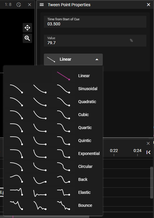
TRANSITIONS
As seen in the last image, there are a few Transitions to choose from. Linear is the default one, then there are some with different kind of smoothness, from Sinusoidal to Circular. Back, Elastic and Bounce add a special twirl to the Effect curve.
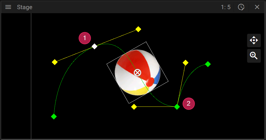
POSITION EFFECT
The Position Effect is quite different compared to other effects. Like other effects you can see the tween points in the Effect curve view. But the value of the tween points can not be changed by dragging the tween point up/down in this view. That is because the value of this Effect is the position of the Cue on Stage, which consists of three values: X, Y and Z. Thus, the Position Tween Points can also be viewed, selected and dragged in the Stage window.
Start creating an animated Position Effect like this:
- Select a media Cue.
- Activate the Position Effect in the Effects menu, or by right clicking the Cue and locate the Position Effect that way.
- Move the Timeline marker forward a bit, eg towerds the end of the Cue.
- Click and drag the Cue in the Stage window, to a new position
It should look something like this:
Move the Timeline marker between the two points, and you can see that the position of the Cue on Stage is animated between these two positions. You can keep adding more points by placing the Timeline marker and moving the Cue on Stage. You can also, as with other Effect curves, click on the curve in the curve view, to add more points.
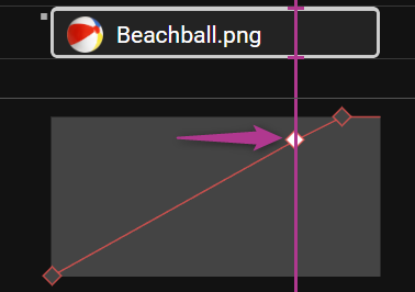
VISUALIZES MOVEMENT SPEED
The Position Effect curve does not represent the value of the Position Effect, but the progress along the Position Effect curve. This is why the first point is allways at the bottom of the curve view, as this is the beginning of the curve, and the last point is at the top, corresponding of the end of the curve. To demonstrate how this can be helpful, here is an example:
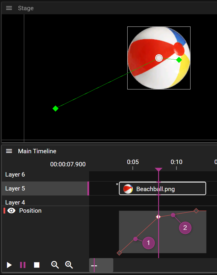
As you can see, the two last points are placed close to each other on the Stage, but on the Timeline, in the Effect curve view, you can see that they are spaced further apart. This means that the movement speed will differ when playing back this animation, it will slow down when moving past the second point. You can see this in the Effect curve, by looking at the incline of the curve: higher incline means higher speed (1), and lower incline means lower speed (2).
By moving the middle point to the left on the Timeline, until the incline of the segment before and after the point are equal, you get movement with the same speed across the animation.
POSITION EFFECT PROPERTIES
Here you can, besides setting the expressions to control the three values of this Effect (X, Y and Z), set the ORIENT CUE ALONG PATH property of the Effect. Setting this property will make the Cue rotate, to orient itself along the direction of the movement curve. It may look something like this:
POSITION TWEEN POINTS
Position Tween Points are visible as green diamonds in the Stage window, when the cue they belong to is selected. Here they can be selected, dragged around, and deleted. In the Effect curve view, only their time value can be dragged, as mentioned before. If you switch the Stage to the First Person mode, you can move the points in all directions using the axis gizmo.
POSITION TWEEN POINT PROPERTIES
Besides the position value of the tween point, you can edit the following:
SMOOTH HANDLES
Set the Smooth In and/or Smooth Out properties to get handles to control the direction of the position curve. Use these to generate non-linear curves between the position points on Stage, to get a "smooth" movement animation. The control handles are visible as yellow diamonds in the Stage window. They can be linked or unlinked, using the Linked Handles property. See this example: (1): Linked handles; (2): Unlinked handles.
Use linked smooth handles together with the speed visualization, to get a guaranteed smooth movement animation.
TRANSITION
Use Transitions to control the speed of movement across the position curve. For example they can be used to stop the animation smoothly on a point, and then smoothly accelerate up to speed again.
DEVICES & NODES
Devices and nodes play a central role when setting up a WATCHOUT show and in this chapter you will learn about what devices and nodes are and how they can be configured.
DEVICES
At a very general level you can think of a device as something that transforms data. The device receives an input data stream and transforms that into an output data stream.
WATCHOUT supports the following device types:
- Display
- This device type is used to configure how cues are recorded and how the recorded cues are presented in a show.
- Capture
- This device type is used to configure how video (and audio) streams can be captured and rendered by using a capture cue.
- Audio
- This device type is used to configure the playback of audio in a show.
A node represents a machine, like a WATCHPAX, on your network and devices usually need to be associated with a node to become fully functional.
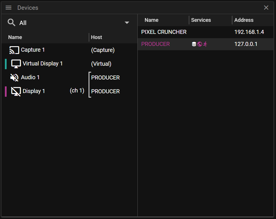
DEVICES WINDOW
The Devices window is divided into two vertical panes:
- The left pane shows the available devices in the show.
- The right pane shows the available nodes on the network.
- A node represents a machine on your network.
Each pane has its own context menu and you may access the context menu by right-clicking on the items in the two panes.
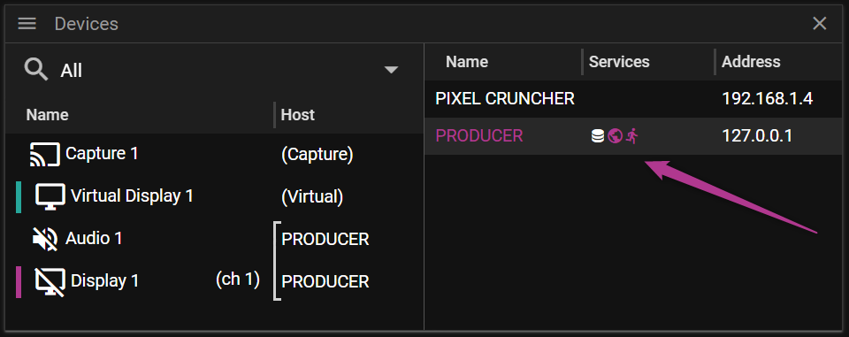
DEVICES WINDOW RIGHT PANE
This part of the Device window shows the available computers, also referred to as nodes, on the network. It consists of three columns:
- Name shows the name of the node.
- Services shows the services provided by the node.
- Asset Manager uses a stacked disc icon
- Director uses an earth icon.
- Runner uses a running man icon.
- Address shows the IP-address of the node.
You may sort the items in the device list by clicking on the column labels.
Producer uses a discovery system which means that it continuously scan for new available nodes on the Network. It also detects if a node is no longer available on the network by displaying the node name using red color.
By right-clicking on a node you will open a context menu where you can find actions that can be performed on the selected node.
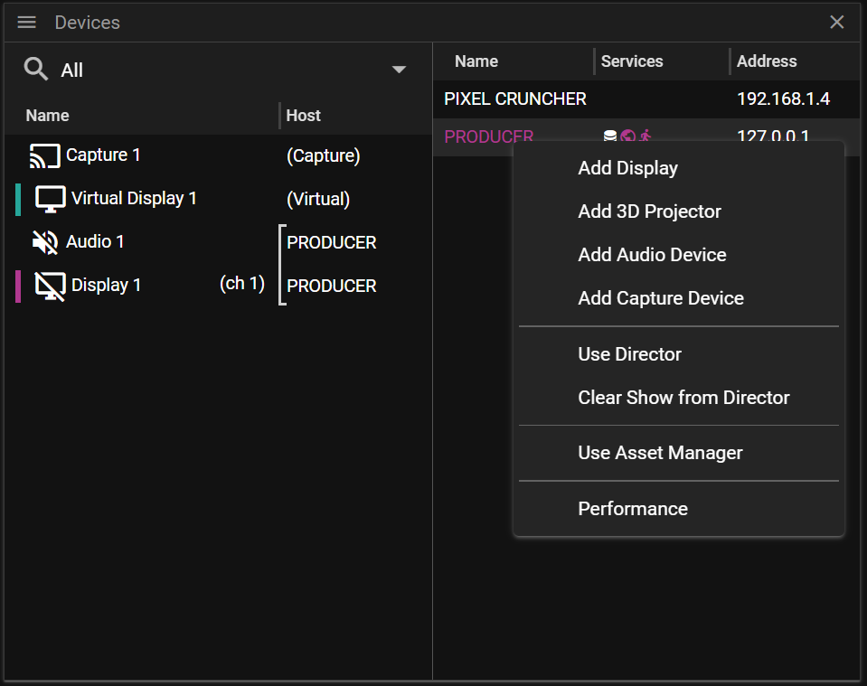
- Add Display creates a new display on the selected node.
- Add 3D Projector creates a new projector on the selected node.
- Add Audio Device creates an Audio Device which requires play sound.
- Add Capture Device creates a Capture Device which is required for NDI streaming etc.
- Use Director pushes the show currently loaded in Producer to the targeted Director, actively replacing any show previously handled by the targeted Director.
- Clear Show from Director clears the show currently handled by the targeted Director.
- Use Asset Manager uses the target node as the Asset Manager for the show.
- Performance opens a page showing information about the targeted node. For instance you can get information about the available CPU, GPU and HDD.
SERVICE STATE
Your node name, the machine running Producer, is displayed using pink color. Pink color is also used to indicate if a Director or Runner is occupied. The Asset Manager is not colored pink because sharing an Asset Manager is considered to be safe and in a lot of situations preferred. That being said, if you rearrange assets in the Asset Manager you probably want to coordinate this with your team.
NODE CONNECTION LOST
If you lose connection to a node it will be colored red as shown in the image below. This can for instance happen if a computer has been idle for a period of time and the computer goes into sleep mode.
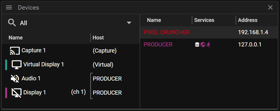
If the node has not been seen on the network for five minutes it will be removed from the list of available nodes.
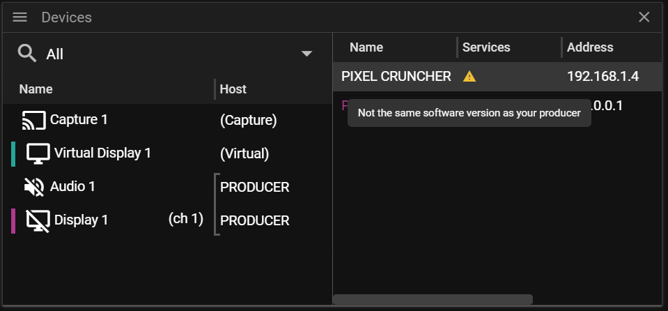
NODE VERSION WARNING
If the version being in use on Producer is not matching the version used on a specific node this will be indicated by using a yellow warning triangle. Using different versions on nodes can work but it is recommended to use the same version on all nodes utilized for show creation and playback.
DEVICES WINDOW LEFT PANE
This part of the Device window shows a list of the devices that have been added to the show.
- Name shows the name of the node.
- Host the name of the node it is associated with.
You may sort the items in the device list by clicking on the column labels.
If a device is selected the Device Properties will be populated with information and editing possibilities for that device. You may select multiple devices by holding using control (or shift) when clicking on devices in the device list. This can be very useful if you want to edit the same property for multiple devices in a single operation.
By right-clicking on a device you will open a context menu where you can find actions that can be performed on the selected device(s).
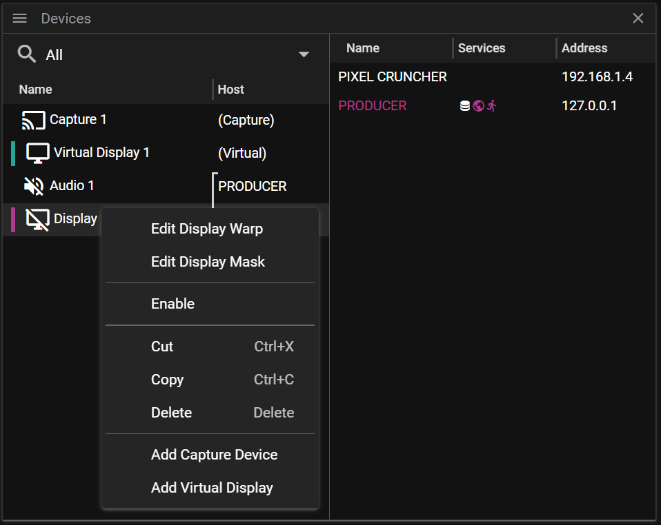
- Edit Display Warp allows you to edit the warping for the display.
- Edit Display Mask allows you to edit the masking for the display.
- Enable activates the device.
- Enabling a device can also be done by pressing the heart icon, as shown here Display Properties.
- For instance, enabling a display device will make it render the cues that are inside the display.
- Cut cuts the selected device(s) allowing you to paste the device(s) later on.
- Copy copies the selected device(s) allowing you to paste the device(s) later on.
- Delete deletes the selected device(s).
- Add Capture Device creates a Capture Device which is required for NDI streaming etc.
- Add Virtual Display creates a new virtual display.
DEVICE FILTERING
If you have many devices in your show it may be useful to filter out specific device types, as shown below:
NODE PROPERTIES
In this chapter you will learn about the available node properties. These properties will populate the Properties window once a node has been selected.
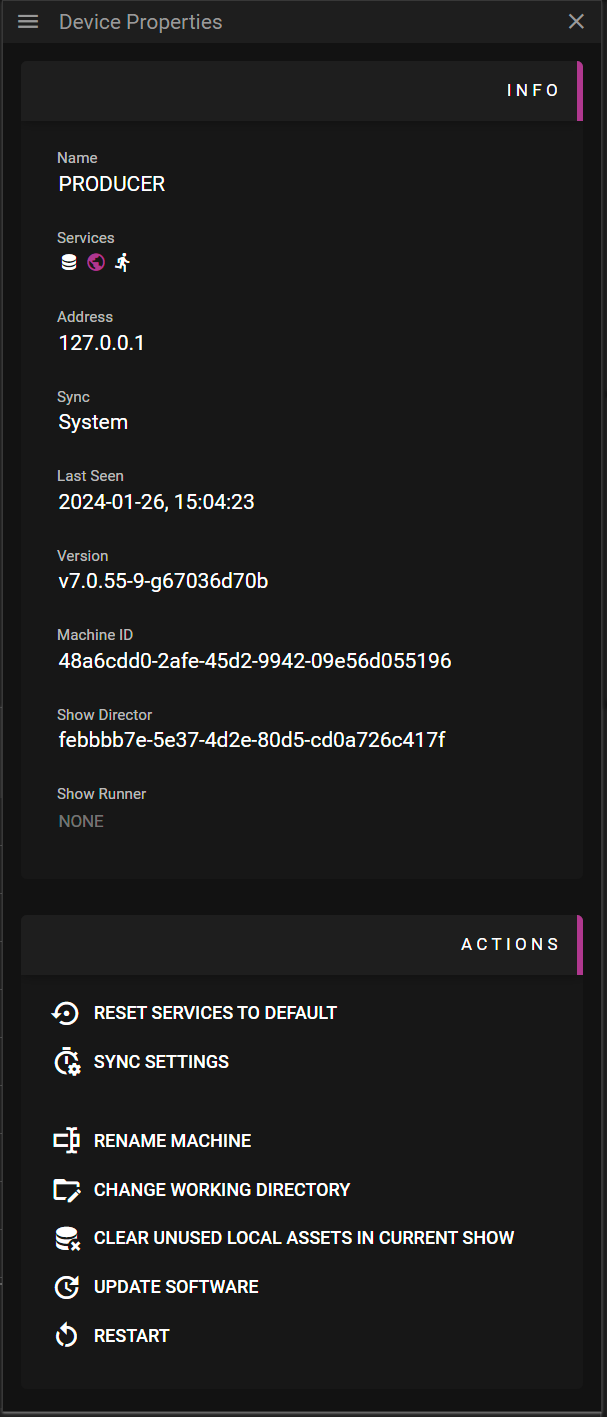
INFO
In this section you can find information about a node that has been selected in the Devices window. This section is only shown if a single node is selected, otherwise it is hidden.
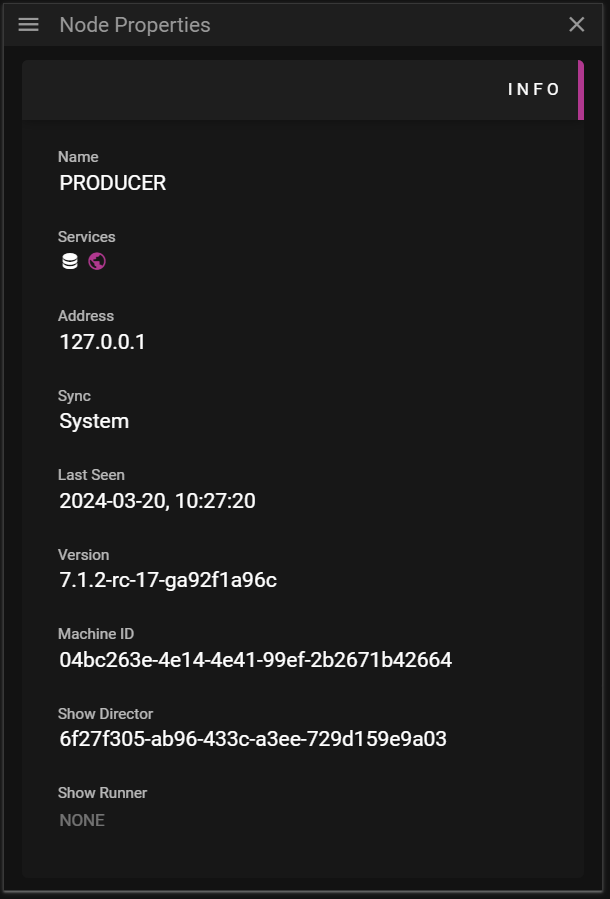
- Name of the node.
- Service the node provides.
- If the Director or Runner is occupied the icon is colored pink.
- Sync shows how NTP is synced on the node.
- Last Seen shows when the node was last seen on the network.
- Version shows the version of WATCHOUT the node is using.
- If a warning icon is shown it means that the node does not run the same version of WATCHOUT as Producer.
- Machine ID shows a uuid that WATCHOUT uses to identify the node on the network.
- Show Director shows a uuid for the show that is currently loaded on the Director existing on the node.
- This is set to NONE if there is no show loaded on the Director.
- Show Runner shows a uuid for the show that is currently loaded on the Runner existing on the node.
- This is set to NONE if there is no show loaded on the Runner.
ACTIONS
In this section you find the available actions that can be executed on the selected node(s).
Many actions that can be performed here must be used with great care since they may be destructive to your setup.
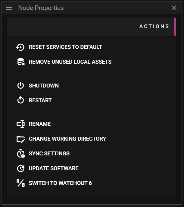
- Reset Services to Default restarts the services on the selected node(s) and shows the splash screen.
- Remove Unused Local Assets removes all assets that are not referred to by the show currently loaded in Producer.
- It may be useful to free space on nodes but it also means that the node must download new assets for previously played shows.
- Shutdown allows you to shutdown the machine associated with the node.
- Restart allows you to restart the machine associated with the node.
- Rename Machine allows you to rename the node representing your machine.
- This action can only be performed on a single node at a time.
- Change Working Directory allows you to change the working directory for WATCHOUT.
- The working directory is where essential WATCHOUT data, such as assets, is stored.
- This action can only be performed on a single node at a time.
- Sync Settings allows you to override the WATCHOUT clock synchronization between all the nodes used in your show.
- By default WATCHOUT configures this for you but you may decide to do this in a custom way by disabling the WATCHOUT time sync.
- Use at your own risk since it may result in nodes playing frames out of sync.
- Update Software allows you to update the WATCHOUT software version on the selected nodes to use the same version that is currently running your Producer.
- Switch to WATCHOUT 6 allows you to switch the selected nodes to using WATCHOUT 6 and restart the machine(s).
- This will only affect nodes associated with WATCHPAX servers.
CAPTURE
A capture device allows you to capture data streams produced by various sources. WATCHOUT supports capturing NDI® streams, video streams from live cameras etc.
The captured stream can be added to a WATCHOUT show as a cue. Then you may add effects can further tweak how the captured stream is rendered.
To set up a capture stream you need to:
- Create a capture device.
- Add a stream to the device.
- Drag the device to a Timeline which will create a cue referring the captured stream.
CAPTURE PROPERTIES
In this chapter you will learn about the available Capture Properties.
GENERAL
This section contains the possibility to set a name for the capture device and define the resolution for all cues that will be referring to the captured stream.
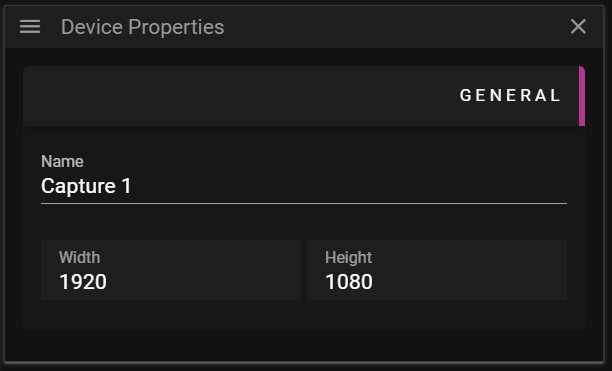
- Name a user defined name for the capture device.
- Width defines the width, in pixels, of the cue associated with the stream being captured
- Height defines the height, in pixels, of the cue associated with the stream being captured.
SOURCES
This section gives you the possibility to configure which streams the capture device should listen to.
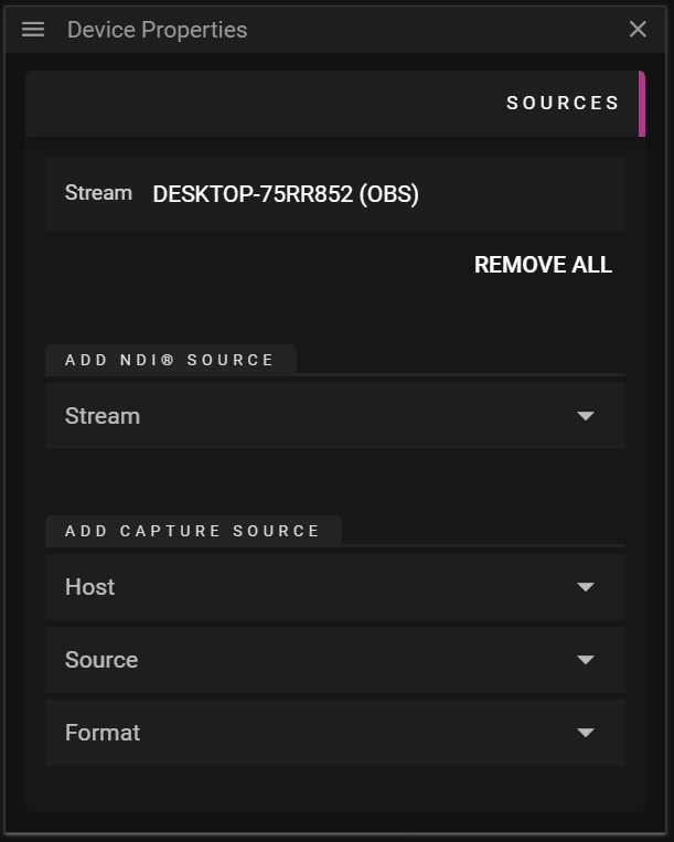
- Streams List shows a list of the streams that this capture device will listen to.
- Remove All removes all streams that have been added to the capture device.
- The order in which streams appear in the list will decide the order in which we try to display streams. Streams are prioritized from top (highest priority) to bottom (lowest priority). If the topmost stream in the list is unavailable WATCHOUT attempts to stream the one below it etc.
- Remove All removes all streams that have been added to the capture device.
- Add NDI® Source
- Stream lists all available NDI® streams.
- Add Capture Source
- Host defines the name of the host/node/machine to create a capture stream from.
- Source lists all available, non NDI®, streams that can be captured on the selected Host.
- Format defines the format to use for the stream.
VARIABLES & EXPRESSIONS
Variables can be used to control and influence the behavior of WATCHOUT. They can get their value from external input, tweens or other variables.
Why use variables
- Variables can start, pause or stop a timeline
- Variables can be used to set effects
How do variables get their value
- From external input
- From user dragging the slider
- From other variables, via a variable cue
- From tweens on a variable cue
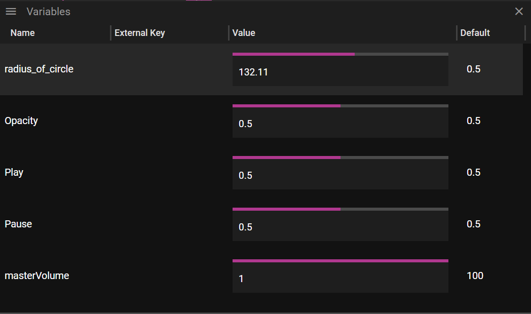
Picture above shows the Variables window. To create a variable choose Add Variable from the menu located in the upper left corner of the Variables window.
Double or single click on a variable to get to its properties.
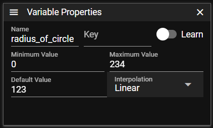
Variable properties includes
- Name, name of variable
- Key, input key that can be learned
- Minimum Value/Maximum Value, minimum and maximum value the variable can have
- Default Value, the default value the variable will have at startup
- Interpolation, the way the system interpolate between the incoming values
- None, no interpolation
- Linear, linear interpolation that, if needed, adds values between two input values
OSC VARIABLE
WATCHOUT can accept osc (open sound control) which is a protocol for controlling multimedia devices over a network. in the example below, Touch osc is to demonstrate the osc input. Touch OSC is a mobile app (avail- able on apple app store or Google Playstore) that lets you create customizable touch interfaces. These are used to control software and hardware applications through touch gestures. The app has a number of built-in layouts or you can use the Touch Editor software to design your own interface with buttons, sliders, rotary knobs and other touch elements. These can then be wirelessly connected to your WATCHOUT Producer computer.
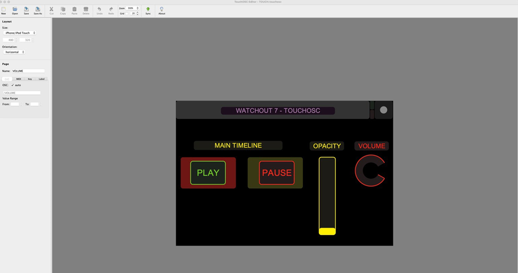 once you have designed your interface, transfer the layout to a smart phone. Now connect the Touch OSC app to the WATCHOUT Producer using the iP address of the Producer.
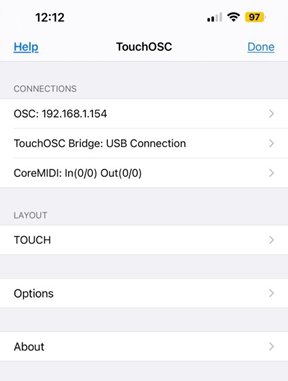
EXAMPLE
in the Producer software, open the Variables window from the Window menu. a volume variable is shown by default.
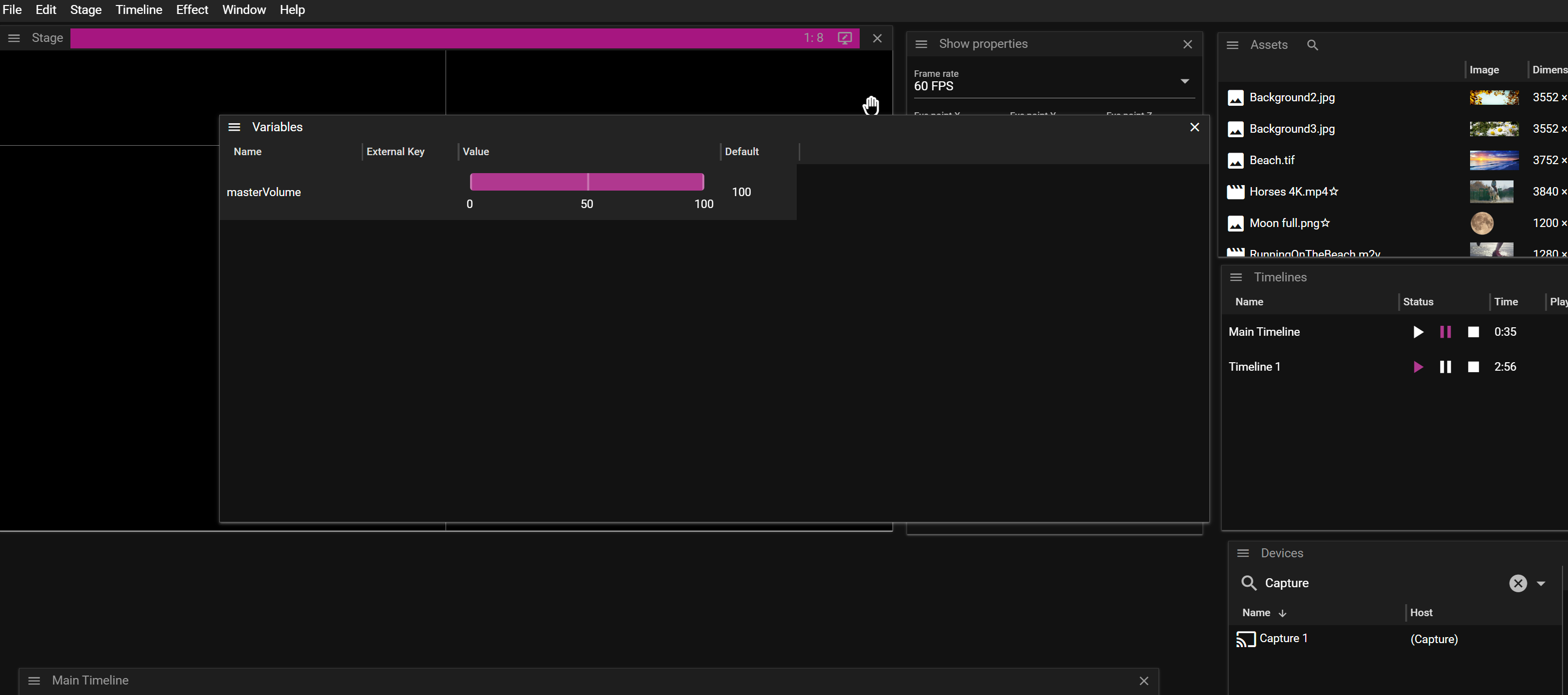
click on the hamburger menu in the top left of the Variables window and select “add Variable”.
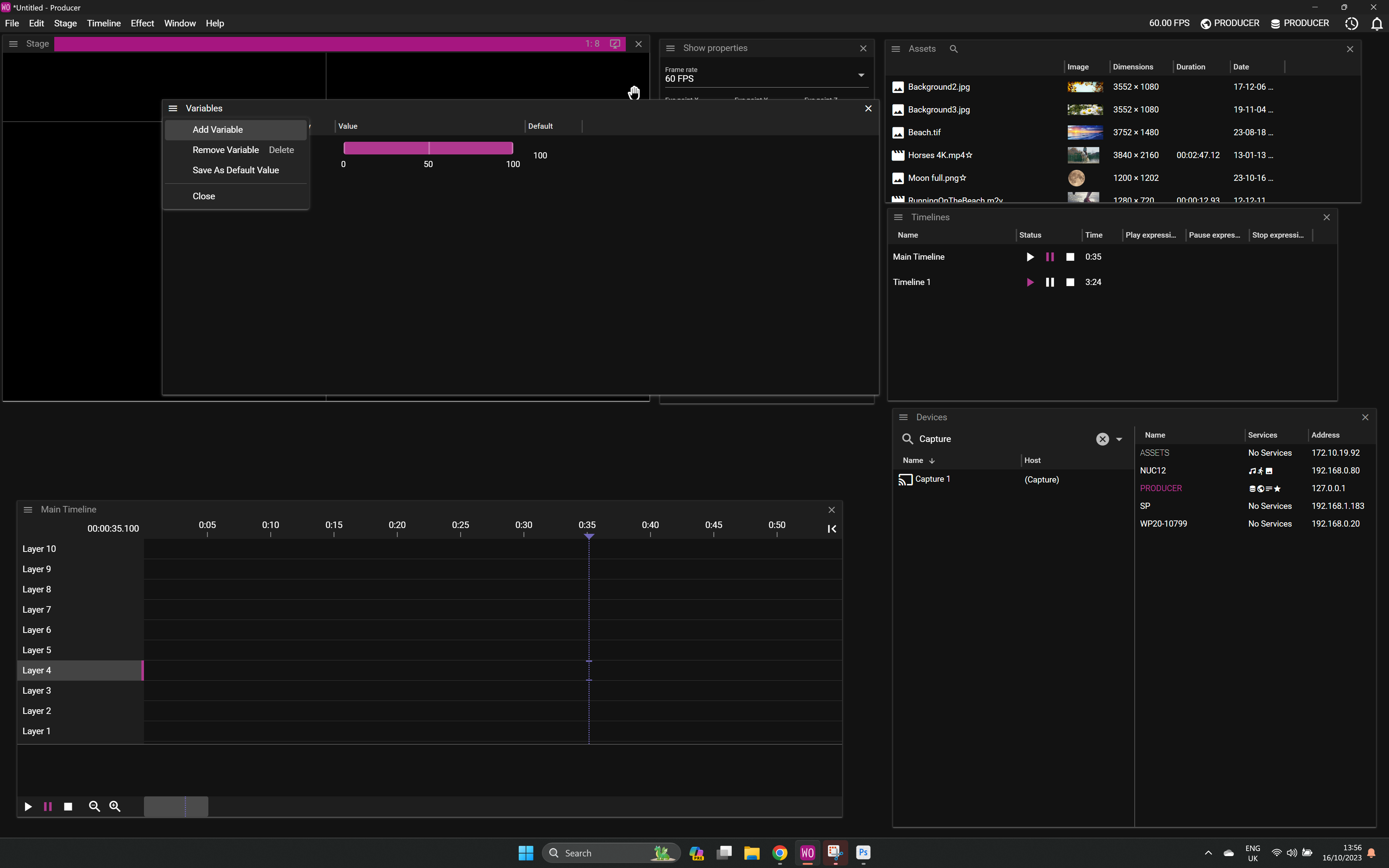
double-click on the Variable to bring up the Variable Properties window. Give the variable a name, click on learn and then activate the relevant Touch osc control. WATCHOUT will show it in the drop- down list in the inputs window. Test that the input is working by triggering the Touch OSC control. The value should go from 0 to 1.
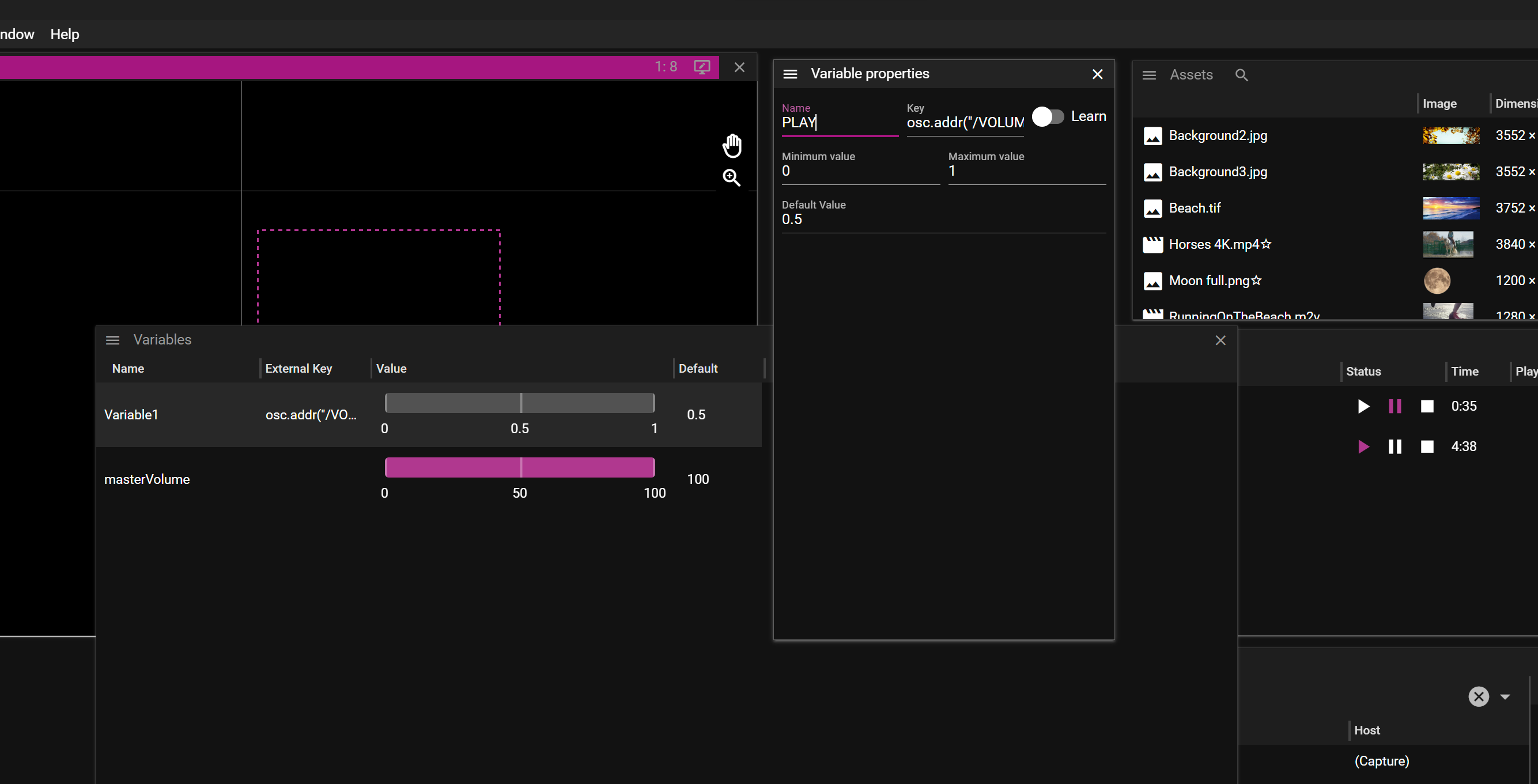
assign the Variable to a timeline in that timeline’s properties window.
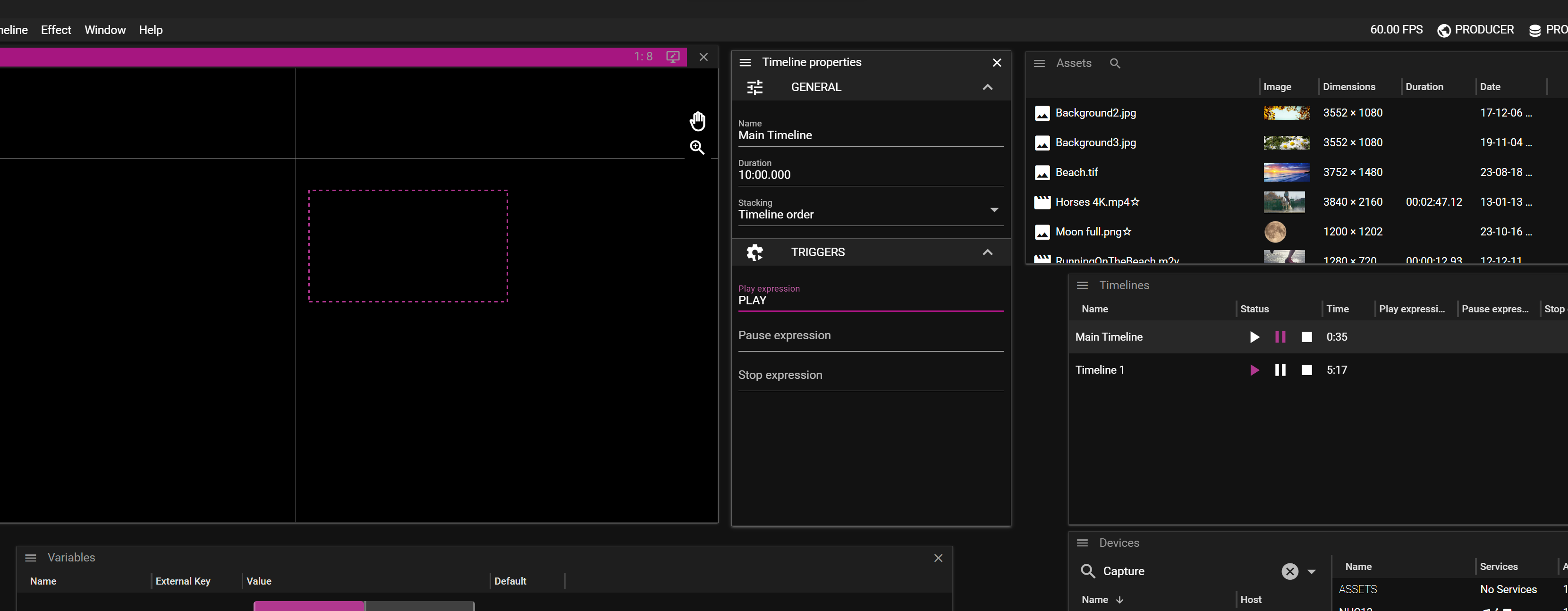
The same process applies to an Effect. in the example below, the fader is used to control opacity on a media cue.
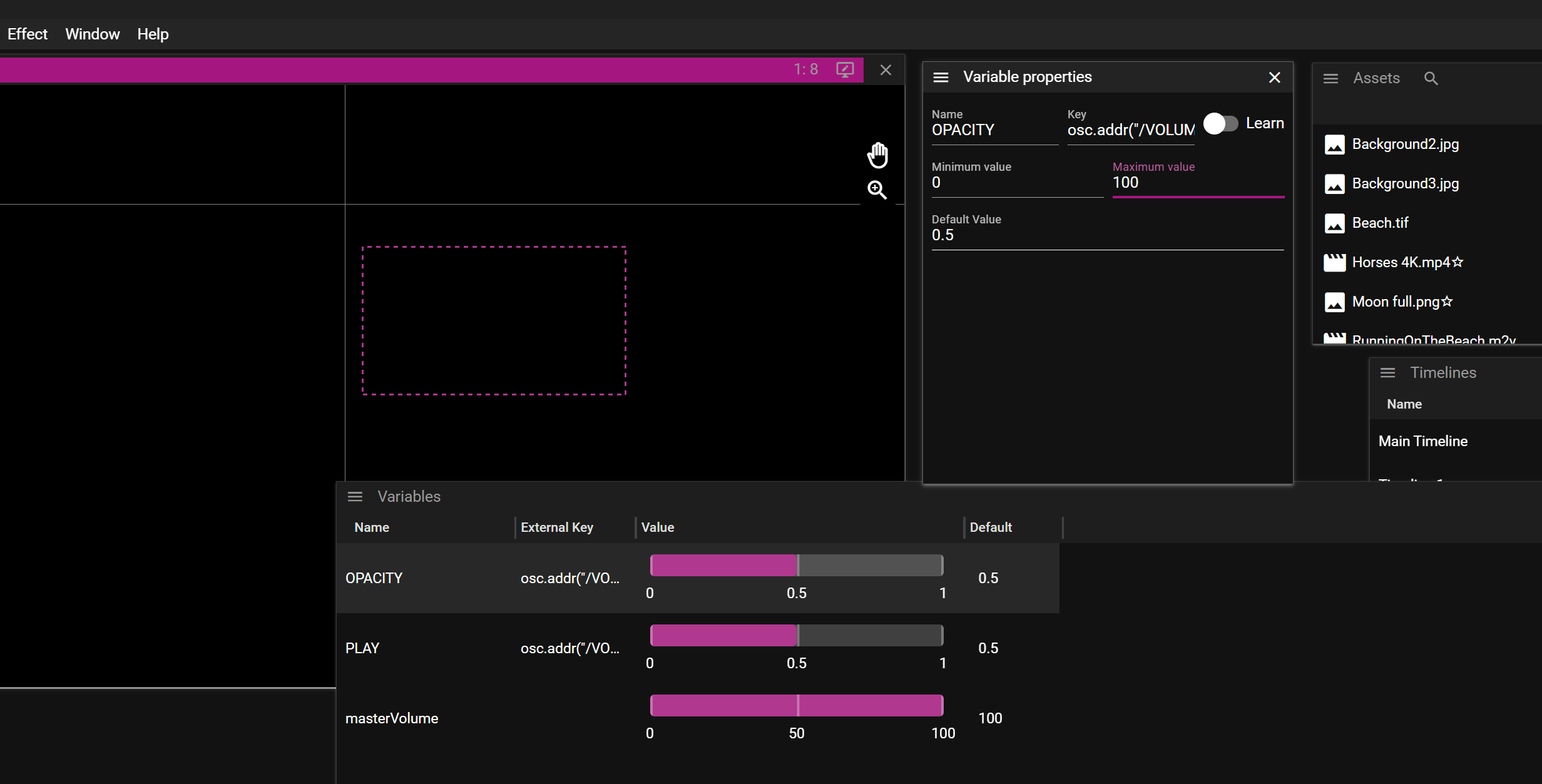
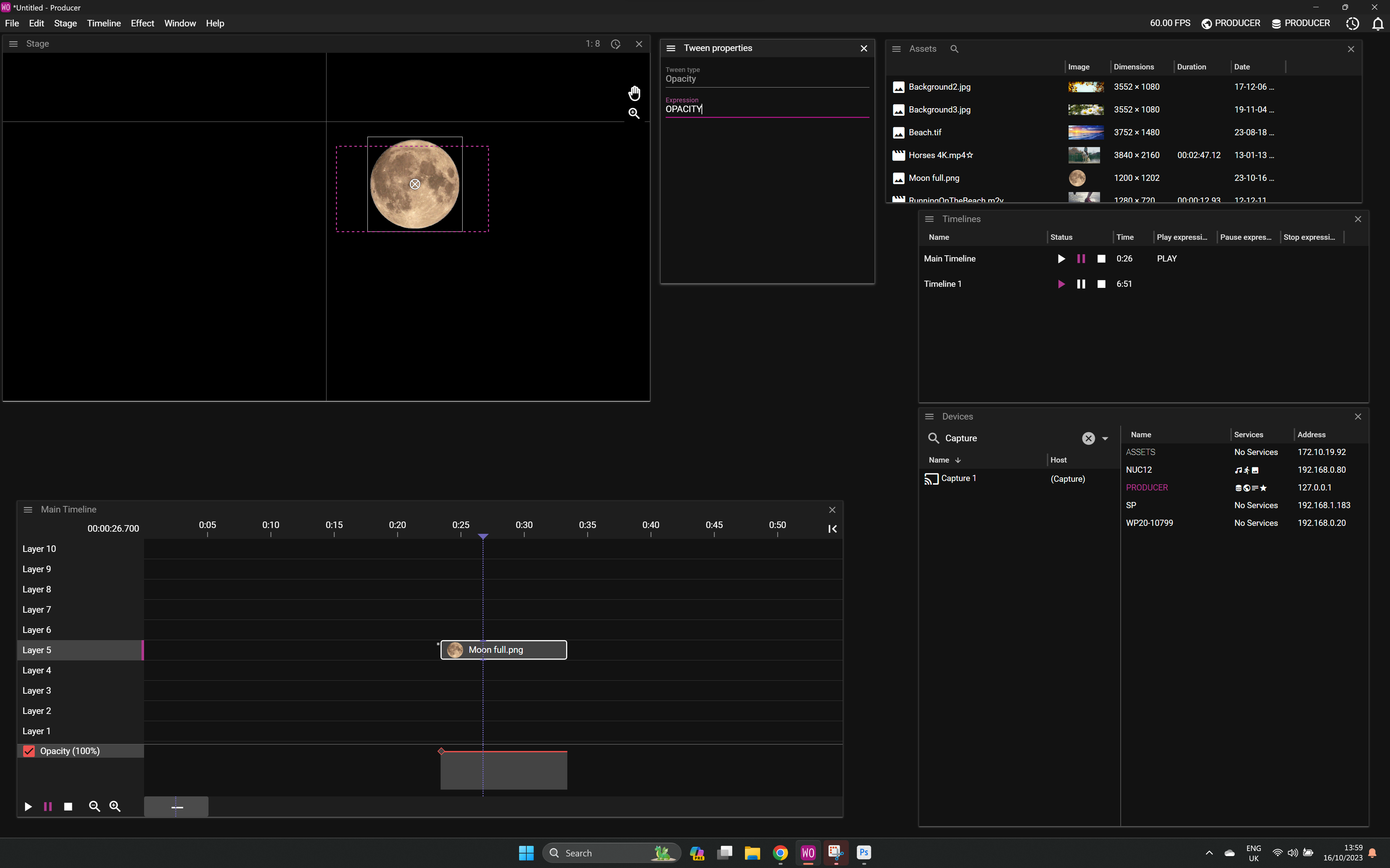
FAQ
Q. What port does WATCHOUT use for OSC?
A. 8000.
Q. Does WATCHOUT support OSC over TCP?
A. No, only UDP works.
Q. Where can I learn more of OSC?
A. More information about Open Sound Control (OSC) can be found on Wikipedia.
DMX VARIABLE
As WATCHOUT does not directly support DMX input, you have to use an Art-Net adapter which converts DMX to Ethernet. Once converted, you add a Variable.
NOTE: You need to manualy give the Variable key the name “artnet.uv(1).ch(2)” to pick up channel 2 on Art-Net universe 1.
You also need to manualy set the Variable scale to Min Value 0 / Max Value 255.
More information about Art-Net can be found on Wikipedia
MIDI VARIABLE
WATCHOUT 7 has a separate app for MIDI control, which can be installed on the Producer node.
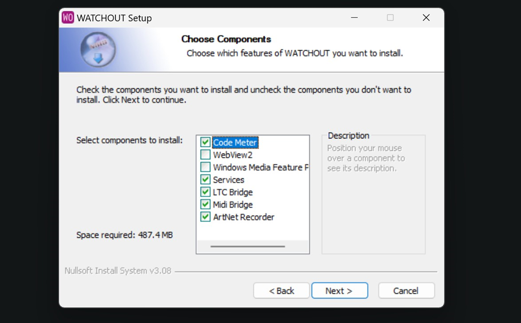
Open the MIDI Bridge app and then choose the MIDI device to use.
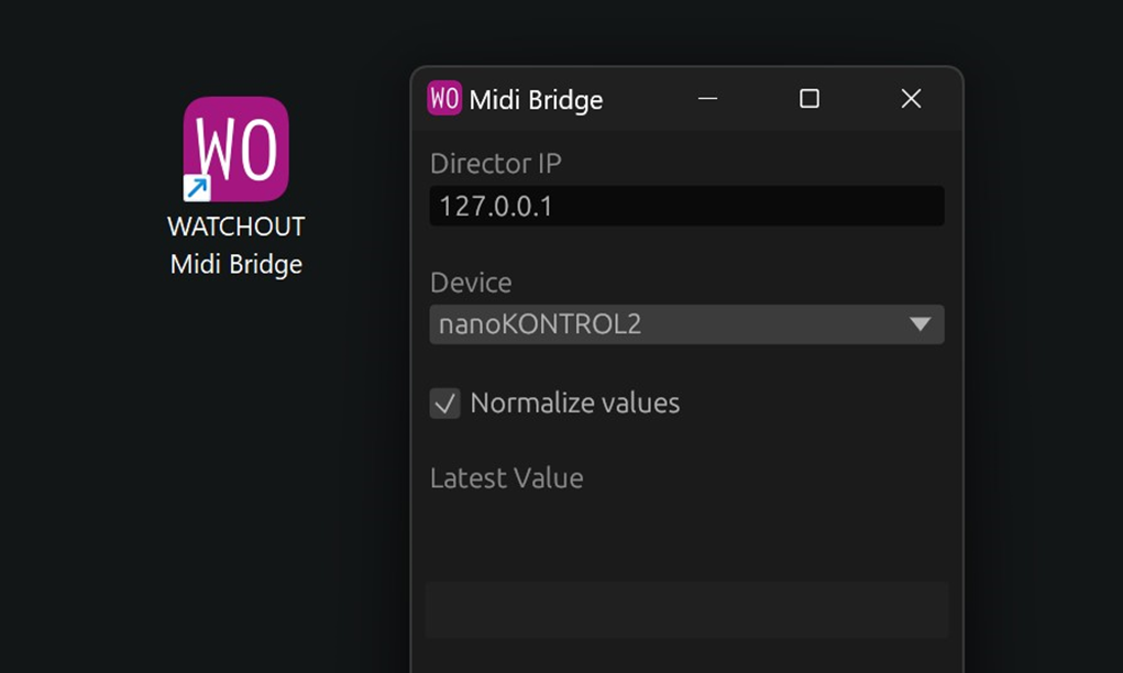
FAQ
Q. What computer shall I run MIDI Bridge on?
A. The MIDI Bridge can run on any computer, as long as it can connect to the Director of the show.
Q. Can i run more than one instance of MIDI Bridge on one computer?
A. Yes, example if you want to use more then one MIDI device at the same time, you need to connect them to different MIDI Bridges.
Q. Shall I use normalized values?
A. In most cases yes. Normalized values gives you a value between 0 and 1. Otherwise you will get a value between 0 and 127.
LTC INPUT
LTC (Linear Time Code) is time code data encoded into an audio signal. LTC Bridge listens on a audio interface for this code, and the it controls time on at least one timeline.
LTC Bridge looks like this
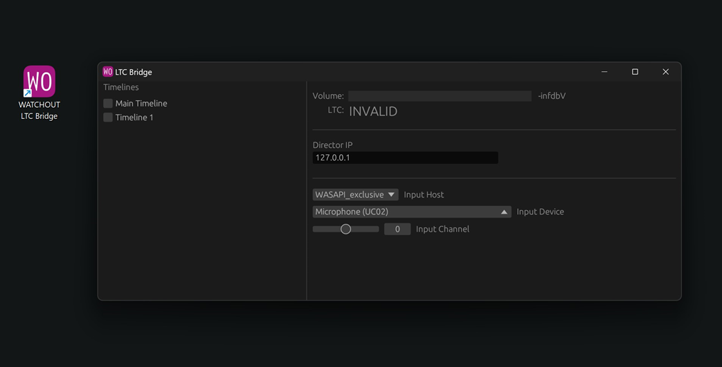
Choose the input type and Host.
Timelines will show the available Timelines in the WATCHOUT show that can be controlled.
FAQ
Q. Can I control more tha one timeline?
A. Yes.
Q. Can I run many LTC Bridge applications at the same computer?
A. Yes, as long as you use different audio interfaces?
Q. What computer shall I run LTC Bridge on?
A. The LTC Bridge can run on any computer, as long as it can connect to the Director of the show.
More information about Linear Time Code (LTC) can be found on Wikipedia
VARIABLE AS A CUE
A variable can be used as a cue if you drag it from the Variable window to a timeline
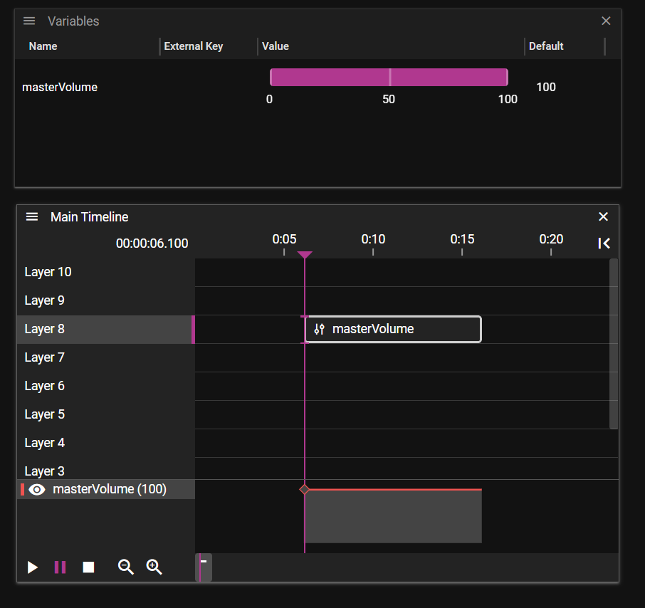
A Variable cue is a way to change the variable value, and always have a effect. This effect changes the value either by a tween track, or by an expression containing other variable(s)
FAQ
Q. When is this useful?
A. If you want a variable that changes depending on timeline time.
Q. When jumping on the timeline the value if variable cue is not updated?
A. the value is only updated if you play into the cue.
VARIABLE PPROPERTY
NAME
The name of the variable.
All names are the same even if they differ in case. This means that "largeCar" and "largecar" will be evaluated the same.
You can tab complete variable names in expressions.
INPUT KEY
This field is needed if you like to control this variable by an extaernal input using MIDI, OSC or Art-Net
You can type the key manually. For OSC and MIDI have the WATCHOUT learn it for you. To learn press the learn button
key example:
- OSC: /1/fader1/0 or /3/xy/y/0
- MIDI: midi.ch(0).cc(7)
- DMX: artnet.uv(1).ch(2)
MINIMUM, MAXIMUM AND DEFAULT VALUE
Minimum and maximum values set the possible range for this variable.
Default value is the value stored in the show file, and is used before input is received or when the system is reset.
As a guide, use these minimum and maximum values for all variables:
- 0-1 – for switches
- 0-100 – for faders
- 0-255 – for DMX
HOW SHOULD THE VALUE BE INTERPOLATED
Input data does not always come each frame. This can cause a rotation to look very bad. Watchout can help you smooth this out if you enable interpolation.
EXPRESSIONS
Everywhere variables are used they are part of an expression. In fact, it is expressions that starts or stops timelines. It is expressions that tells how an effect behaves.
EXAMPLE OF EXPRESSIONS
- "masterVolume" the value of master volume
- "tweenValue" The value of a curve at this point in time
- "tweenValue -1" tweenValue -1
- "1+23/4^5%6 + log(100K) + log(e(),100) + [3(3-3)/3] + (2<3) && 1.23" Random complex expression
- "masterVolume > 0.4" logical expression
FORMAL DEFINITION
Numbers:
- Integers: 1, 2, 10, 100, 1001
- Decimals: 1.0, 1.23456, 0.000001 1 or 1.0 is true 0 or 0.0 is false
Operators:
- () Parenthesis
- ^ Exponentiation
- % Modulo
- / Division
- * Multiplication
- - Subtraction
- + Addition
- == != < <= >= > Comparisons (all have equal precedence)
- && and Logical AND with short-circuit
- || or Logical OR with short-circuit
Functions:
- e() -- Euler's number (2.718281828459045)
- pi() -- π (3.141592653589793)
- int(val)
- ceil(val)
- floor(val)
- round(modulus=1, val)
- abs(val)
- sign(val)
- min(val, ...) -- Example: min(1, -2, 3, -4) == -4
- max(val, ...) -- Example: max(1, -2, 3, -4) == 3
- sin(radians) * asin(val)
- cos(radians) * acos(val)
- tan(radians) * atan(val)
- sinh(val) * asinh(val)
- cosh(val) * acosh(val)
- tanh(val) * atanh(val)
OUTPUTS
An output is created by right-clicking on the timeline and selecting Add Output Cue.
An output cue is represented by this icon on the timeline. It can be used to send a string message over UDP or TCP.

It has the following properties.

PROTOCOL
TCP or UDP
ADDRESS
The target IP number for the data.
PORT
Port to use for the transmission.
DATA TO SEND
A string containing the data to send. It supports all the usual backslash and escape sequences and all Unicode characters.
Note: 0xff are ignored.
An output string like “\xaaHej\n\tvärlden!\x10\xff” will turn out as:
0020 aa 48 65 6a 0a 09 76 e4 72 6c 64 65 6e 21 10 ff .Hej..v.rlden!..
3D
In this chapter you will learn about working with 3D models and setting up 3D mapping using WATCHOUT.
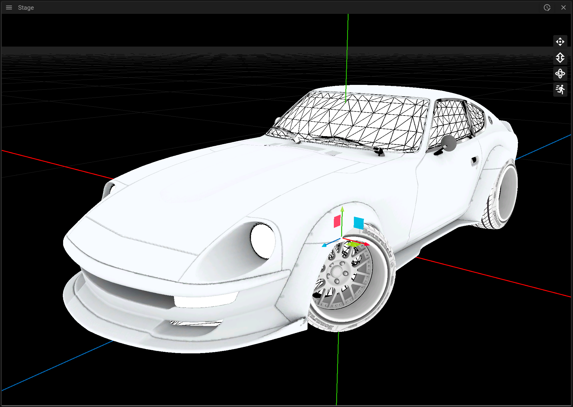
MODELS
In this section you can learn more about working with 3D models in WATCHOUT.
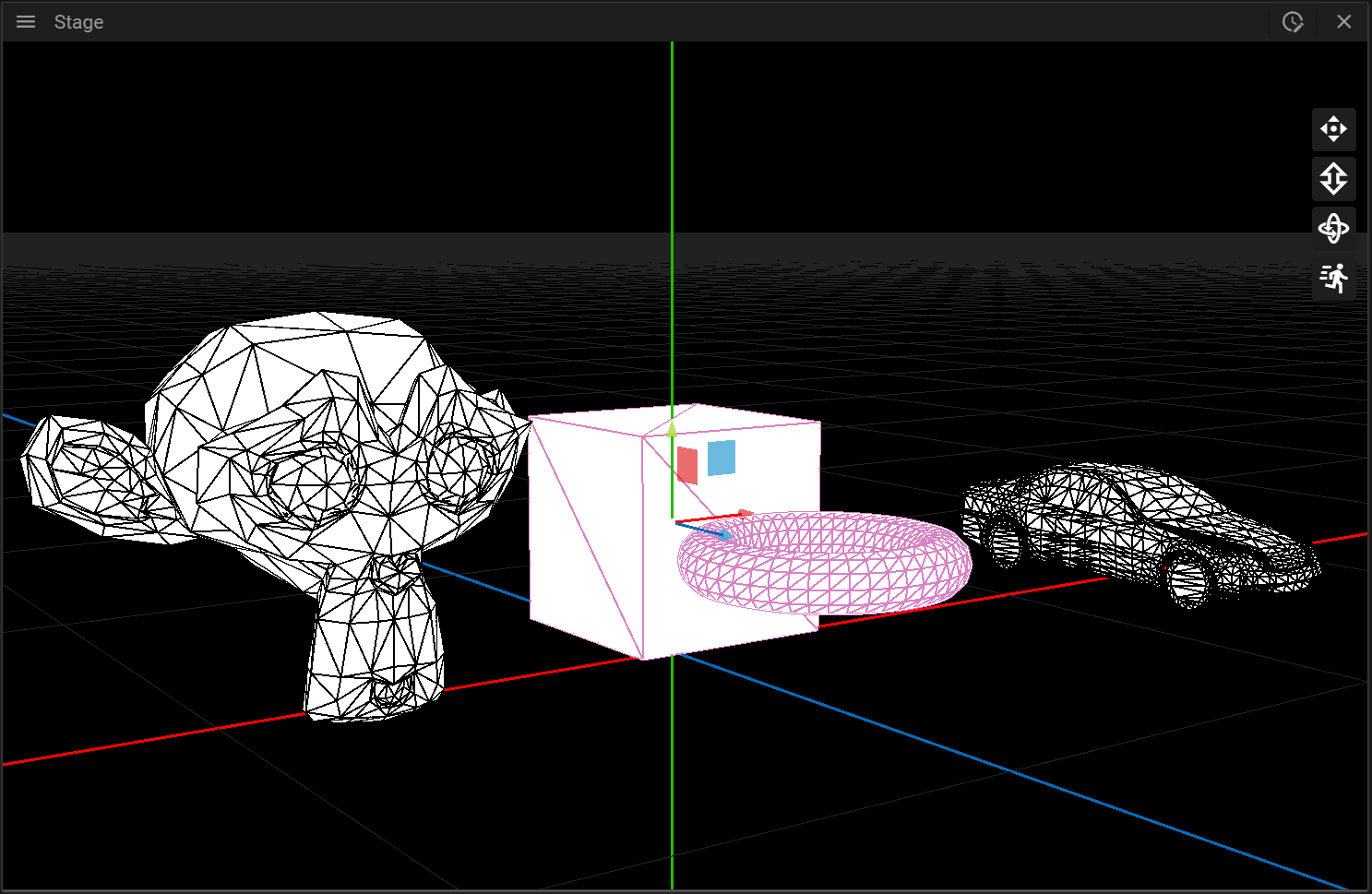
3D MODEL IMPORT
Producer supports import of the following file formats:
- .obj
- .gltf (or .glb)
- .3ds
If you are going to use the imported 3D model for 3D mapping it is required that the model has uv-coordinates.
3D SPECIFIC CUE PROPERTIES
There are two 3D specific properties for cues:
- Size which lets you change the size of the model.
- Surface which shows some information about the 3D asset and lets you remove media that has been applied to the 3D model.
MULTIPLE MESHES
When a 3D model is added to a Timeline a composition is created and each mesh of the 3D model is placed on a separate layer. This allows you to play different media and effects on the different meshes. The mesh names cannot be edited in Producer.
EDIT 3D MODELS
WATCHOUT has very limited 3D model editing possibilities. If you are unhappy with the mesh names or there are visual problems in the 3D model these need to be handled in a program specialized in that, like Blender etc.
3D MAPPING
3D mapping refers to projecting media to fit onto object surfaces, such as statues or cars. The process includes positioning projectors and objects in the real world, creating a virtual scene in WATCHOUT, then calibrating projectors, and projecting media. Calibration involves aligning virtual and real-world points.
To setup 3D mapping you will need:
- One or more objects to project media on.
- One or more 3D models representing the objects you want to project your media on.
- One or multiple projectors.
The setup process can be divided into the following steps:
- Position your projector(s) and object(s) you want to project on in the real world.
- Prepare a virtual scene in Producer by adding and position 3D models and projectors matching the real world from the first step.
- Calibrate each projector by trying to align the virtual scene with the real scene.
- Play media on the surface of the object(s).
In the following sections you can learn about how to prepare a virtual scene and how to align that scene with reality through a calibration step.
VIRTUAL SCENE
To prepare a virtual scene you can begin by dropping a file containing a 3D model representing the real object(s) you want to project on. It is very important that the 3D model(s) closely matches the real object(s) from a proportion perspective, otherwise it will be very hard or even impossible to perform the calibrationstep later. When the Asset Manager has finished preparing the 3D model it can be dragged from the Assets window to a layer on the timeline. It can also be dropped directly to the Stage window.
It is recommended to switch to the [First Person](../stage/stage.md#first-person) camera mode when working with 3D models since this allows you to view and inspect the 3D model freely. A model that still does not have any media/texture applied to it will be rendered using wireframe.
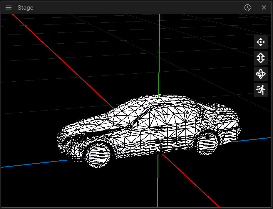
You can change the position of the 3D model by using the axis gizmo or by inputting values in the Cue Properties window.
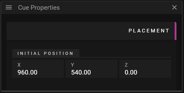
Note that the location of the 3D model in the virtual scene is not important for the 3D mapping to work, it is the relation between the virtual projector and the 3D model that is important. For instance, the 3D model can be placed far away on the x-axis, as long as the projector can “see” it from an angle matching the real-world relationship.
Once the 3D model(s) has been placed in the scene the next step is to add a projector in Producer and position the projector so it can “see” the 3D model(s). To add a projector you can right-click in the Stage window and select Add 3D Projector.
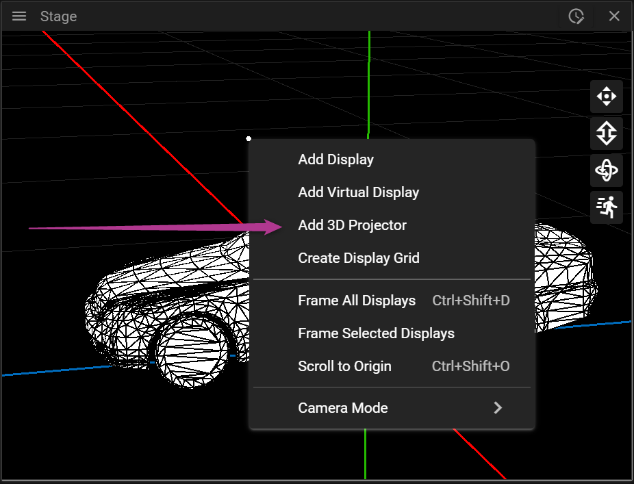
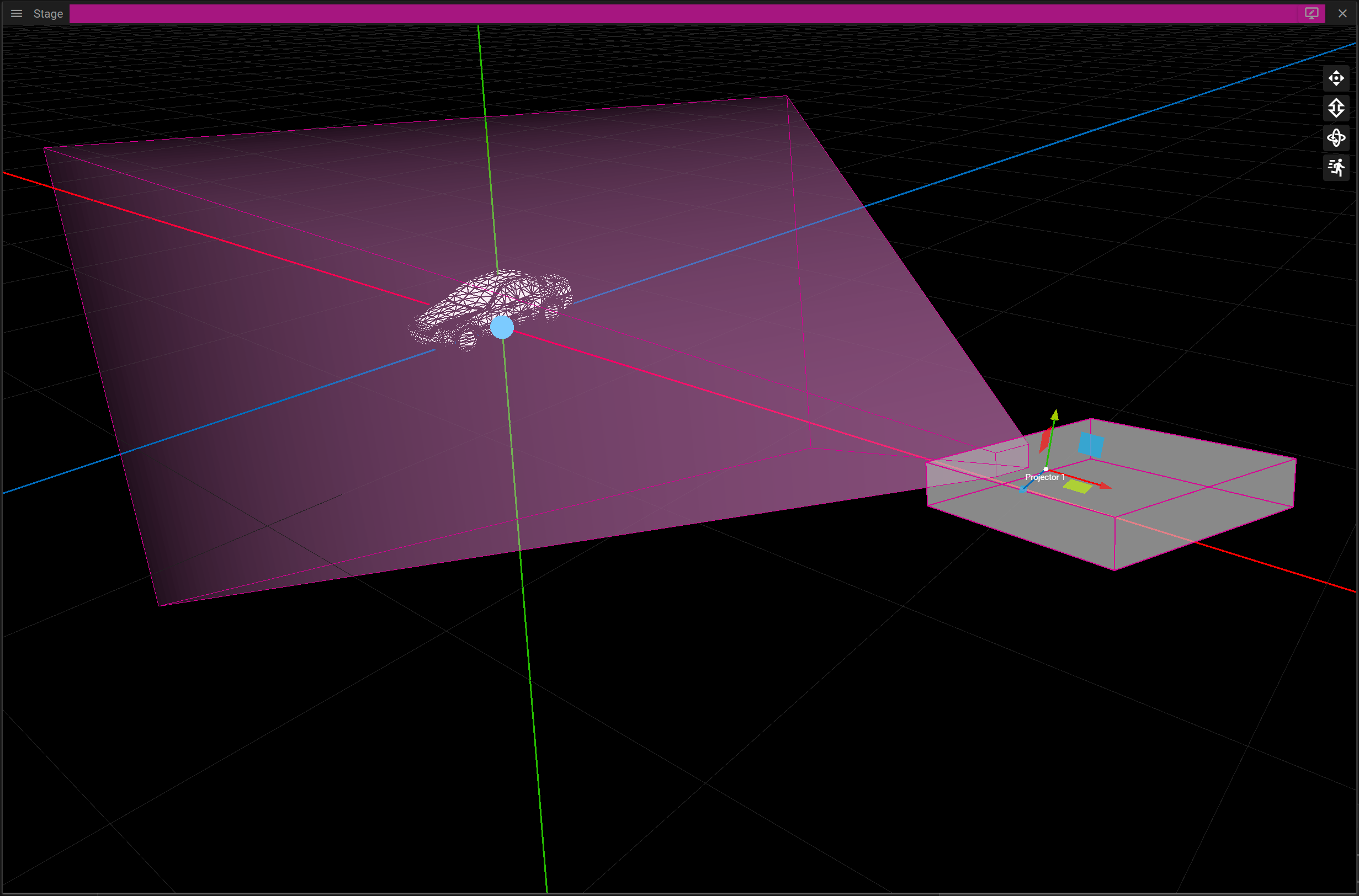
Next you can either change the Target and Eye for the projector in the Display Properties window or you can control the projector as if it was a camera. As an alternative you can position the projector by controlling it as a First Person camera.
To do this you can either click the Frame in Stage button found in the Display Properties window or by double-clicking the projector. This camera mode is referred to as Projector mode.
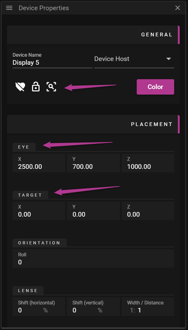
CALIBRATION
Provided you have prepared your virtual scene you are now ready to calibrate the projector. The goal with the calibration is to align virtual points with points existing in the real-world. If done correctly it is possible to seamlessly project media on top of a real object. The calibration process consists of the following sub steps:
- Place virtual points on the 3D model(s).
- Move reality points so they are at the corresponding real location on the real object.
- Align the camera to minimize the distance between the virtual and reality points.
Here is an overview of the UI:
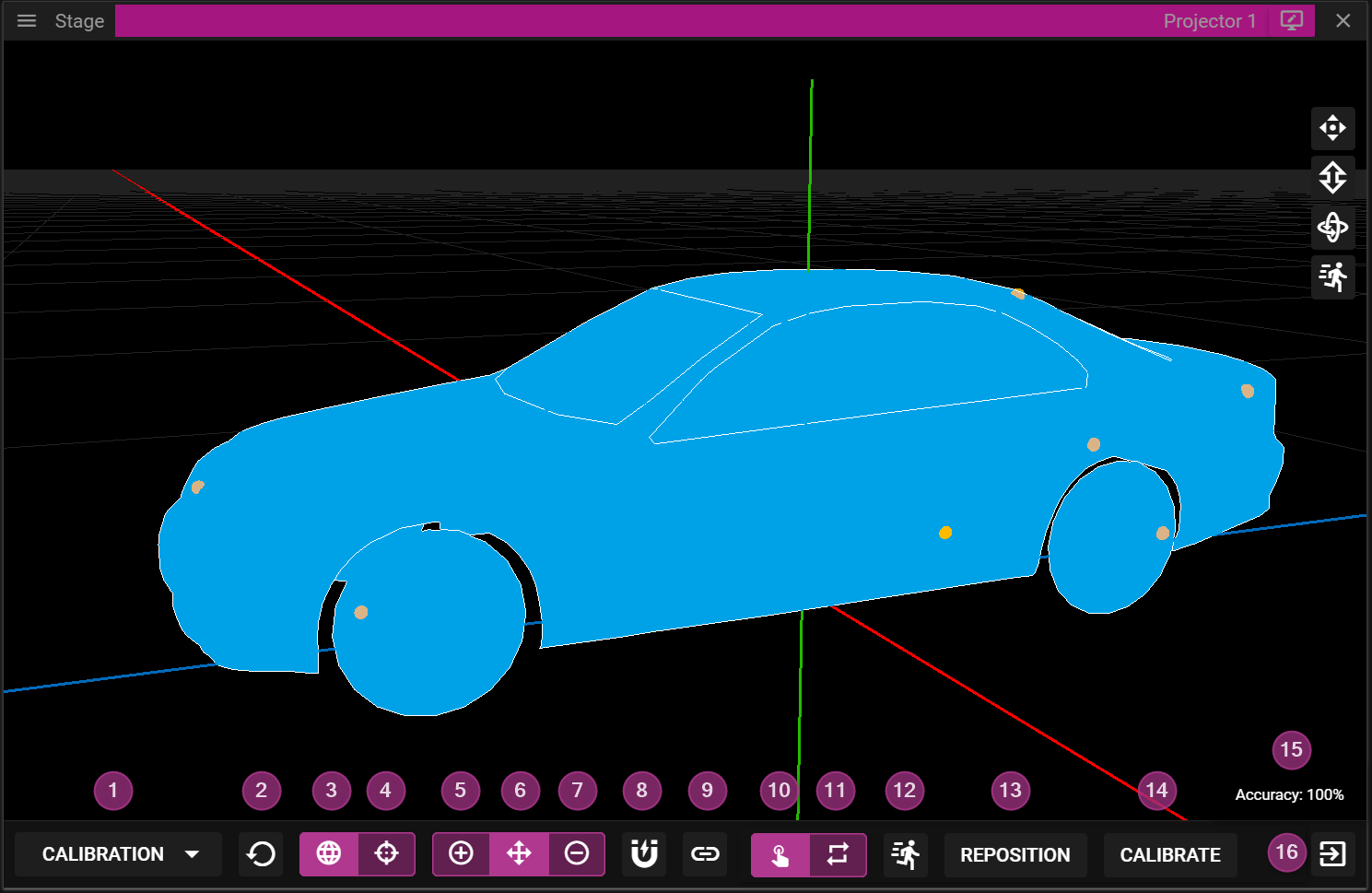
- Switch between View and Calibration mode.
- The projector may only be moved in View mode, for instance by using the W-, A-, S-, D- or arrow-keys.
- Reset the calibration.
- Edit virtual points.
- Edit reality points.
- Add points.
- Move points.
- Remove points.
- Enable/Disable vertex snapping.
- Link/Unlink the projector to the camera.
- Manual edit of calibration points.
- Update the calibration only when the calibrate button (14) is clicked.
- Continous calibration.
- When a reality point is moved the calibration is updated immediately.
- Control the movement velocity for the reality points.
- Reposition the reality points on top of the virtual points.
- Perform calibration.
- Indicates how well the calibration solution could align the virtual and the reality points.
- Exit projector mode.
VIRTUAL POINTS
There are three types of edit operations you can perform when you place virtual points on the surface of a 3D model:
- Add point.
- Move point.
- Remove point.
To add a virtual point, you need to activate the add (+) edit operation and click somewhere on the surface of the 3D model. When a point has been placed it can be moved or removed by activating the other available edit operations. To simplify placing virtual points there is a snapping option that can be enabled or disabled. When the snapping is active, adding and moving virtual points will snap to nearby vertices, basically the points that define the surface of the 3D model.
You may also unlink the projector from the camera to simplify placement of points without moving the projector. You can toggle the linked state by clicking the linked icon. When a projector is relinked to a camera the camera will move to the projector’s POV, not the other way around.
Six virtual points are required to be able to calibrate a projector successfully. More points can be added to further constrain the mapping but please note that more points does not necessarily give a better result.
REALITY POINTS
The reality points are automatically created from the virtual points. These points are not directly bound to the surface of a 3D model but since each reality point is associated with a virtual point they are indirectly bound to the surface of the 3D model.
There are two ways to edit the reality points:
- Manually.
- Continuously.
It is recommended to start by moving the points manually to give an approximation of where the points should be located. To move a calibration point you need select it by left-clicking on it (or close to it). You may also select reality points by using W-, A-, S- and D-keys or by using the left stick on a compatible gamepad. Once selected, a point can be moved by using the arrow keys or by using the right stick of a gamepad. When moving a reality point the goal is to make a virtual point on the 3D model match the corresponding reality point on the real object. For instance, if you select a virtual point located on the lower left corner of a box you want to make the corresponding reality point project on the lower left corner of the box from the real world. Once all reality points have been moved you can click Calibrate to try to align the virtual and reality points with each other.
There is a accuracy percentage label indicating of how well the system can perform this alignment of points. If the label says 100% you have perfect alignment but you can still achieve good results even with lower accuracy level.
In the manual mode it is also possible to Reposition the reality points. If you click that button you will reset reality points placed exactly over the virtual points. This may be useful if you end up in situations where the calibration gives very poor results.
During fine tuning of the calibration process, it might be helpful to activate the Continuous calibration mode. This mode will update the calibration directly when a reality point is moved. If this mode is being used when some of the reality points are far from their correct locations, you might experience severe jumps of the projector making the calibration process hard to complete. So again, only use this mode for fine tuning.
When adjusting the reality points it might be useful to hide the UI overlaying the Stage window. To do so you need to locate the button represented by an eye at the top of the Stage window. Click it to toggle the UI on/off.

VOCABULARY
In this section we gather some common terms that are good to be familiar with when working with 3D content in WATCHOUT.
AXIS GIZMO
An axis gizmo is generally used to move, scale and rotate objects in 3D editors.
MESH
A mesh is a surface composed of a set of connected polygons.
POLYGON
A polygon is a surface defined by three or more vertices. In WATCHOUT each polygon is always a triangle and thereby defined by three vertices. Sometimes polygons are also referred to as faces or just triangles.
TEXTURE
A texture can be thought of as an image that is to be applied to a mesh surface.
UNIFORM SCALING
Uniform scaling means that x, y and z are scaled equally.
UV-COORDINATE
UV-coordinates are used to map an image/texture onto a polygon. UV-coordinates are also sometimes referred to as texture coordinates.
VERTEX
A vertex is a point in space. Three vertices form a triangle/polyon in a mesh.
WIREFRAME
Wireframe rendering means that each polygon edge is rendered as a visible line. The intention with this render mode is often to get a better understanding about the topology and polygon density of a mesh.
AUDIO
In this chapter you will learn about working with audio in WATCHOUT.
AUDIO DEVICES
An audio device is added to a node by right-clicking the node in the Devices window, and selecting Add Audio Device.
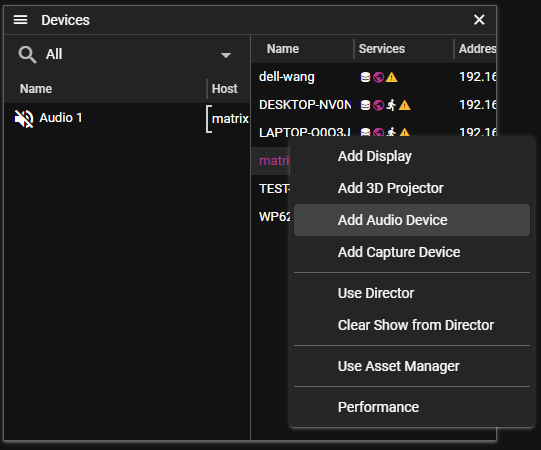
By default the newly created audio device is disabled, and the actual device is unspecified. Leaving the device as unspecified means that the default audio device of the node is used. However, it is possible to select a different device type (WASAPI, WASAPI exclusive, Dante or ASIO), and select a different device. Depending on the device type and capabilities of the device it is also possible to set paramaters such as number of channels, sample rate and delay.
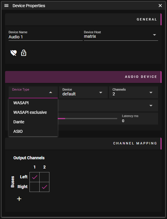
CHANNEL MAPPING
In the first step of channel mapping, the individual channels of an audio cue are routed to audio buses, this is done in the Cue Properties window. By default, there are two buses, named Left, and Right, and the left and right channels of an audio cue are routed to those buses.
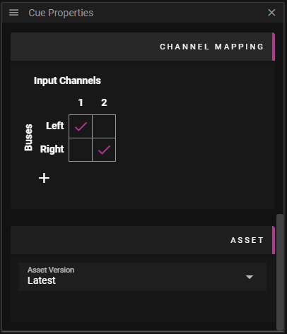
A single click in the channel mapping matrix switches the item from selected to unselected. Double clicking gives the user the opportunity to actually edit the value of the item. By default a selected item means the value is cueVolume, which always has the value of the volume tween for the cue.
The second step of the channel mapping takes place in the Device Properties window. Here is where the mapping of buses to audio device channels are performed. Note that the default value for a checked box in this view is masterVolume, which is a varable that is always present. The user can of course add other variables to use instead of masterVolume, for instance adding a variable monitorVolume and using that in the channel mapping for the audio device carrying monitor audio (e.g. headphones of the operator). Please note that the expression in the channelmapping for audio device shall evaluate to a value between 0 and 100, as opposed to the expression of the cue channel mapping that shall evaluate to a value between 0 and 1.
IMPLEMENTING BALANCE
To implement a traditional balance control for a cue, it is possible to introduce a balance variable, and set the channelmapping for the cue according to the images below.
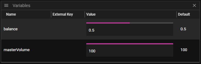
Below is an example of channel mapping for balance control of a cue:
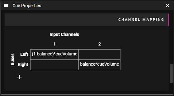
VOCABULARY
In this section we gather some common terms that are good to be familiar with when working with audio.
CUE
An audio cue is a cue on the timeline containing an audio asset.
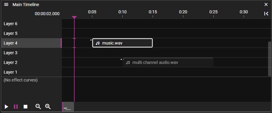
DEVICE
An audio device is a device capable of playing an audio. An audio device is controlled by a runner, and can be of type WASAPI, WASAPI exclusive, Dante or ASIO. A WASAPI, WASAPI exclusive or ASIO device is always hosted on the same machine as the runner, either built-in, or connected via USB, while a Dante device is attached to the network, but controlled by a Dante controller on the runners device. An audio device can have one or more channels, a typical strereo device has 2 channels.
BUS
An audio bus is a virtual mono track collecting tracks channels from one or more audio cues and transmitting onto one or more output device channels. The available buses in the system are numbered from 1 and upwards, but can also be assigned names. By default busses 1 and 2 have the names Left and Right. The available buses are visible in the channel mapping sections of the Cues and devices.
CHANNEL MAPPING
Channel mapping is the process of mapping audio cue channels to audio device channels. This is done in two stages, first stage is in the Cue properties window where the cue channels are mapped to audio buses, next stage is in the Audio Properties window, where the audio buses are mapped onto audio device channels.
EXTERNAL PROTOCOL
OPERATIVE SERVER EXAMPLE USAGE
CURRENT PLAYBACK STATUS
curl.exe http://localhost:3019/v0/state
GET THE CURRENT SHOW JSON
curl.exe http://localhost:3019/v0/show
LOAD ANOTHER SHOW
curl.exe -X POST -H "Content-Type: application/json" http://localhost:3019/v0/show --data @FILENAME
PLAY/PAUSE/STOP TIMELINE BY ID
curl.exe -X POST http://localhost:3019/v0/play/0curl.exe -X POST http://localhost:3019/v0/pause/0curl.exe -X POST http://localhost:3019/v0/stop/0
JUMP TO TIME
- format "/v0/jump-to-time/{tl_id}?time={time}&state={state}"
- {tl_id} is timeline id
- {state} is play or pause
- {time} is given in milliseconds
example
curl.exe -X POST "localhost:3019/v0/jump-to-time/0?time=6000&state=pause"
JUMP TO CUE
- format "/v0/jump-to-cue/{tl_id}/{cue_id}?state={state}"
- {tl_id} is timeline id
- {cue_id} is cue id
- {state} is play or pause
example
curl.exe -X POST "localhost:3019/v0/jump-to-cue/0/0?state=pause"
SEND INPUTS
curl.exe -X POST -H "Content-Type: application/json" http://localhost:3019/v0/inputs --data '[{"""key""": """Tomtar""", """value""": 0.5}]'
LISTEN FOR PLAYBACK UPDATE EVENTS
curl.exe http://localhost:3019/v0/sse
or
curl.exe http://localhost:3019/v0/ndjson
CONTROL WATCHOUT 6 API
ENABLE TCP (DEFAULT)
curl.exe -X POST http://localhost:3019/v0/compat/tcp
DISABLE TCP UNTIL OPERATIVE RESTART
curl.exe -X DELTE http://localhost:3019/v0/compat/tcp
GET TCP ENABLE
curl.exe -X GET http://localhost:3019/v0/compat/tcp
ENABLE UDP (DEFAULT)
curl.exe -X POST http://localhost:3019/v0/compat/udp
DISABLE UDP UNTIL OPERATIVE RESTART
curl.exe -X DELTE http://localhost:3019/v0/compat/udp
GET UDP ENABLE
curl.exe -X GET http://localhost:3019/v0/compat/udp
LEGACY PROTOCOL
We implemented the old version 6 protocol in order to ensure a smooth transition with as less friction as possible. We tried to keep breaking changes to a minimum and all are clearly pointed out in this chapter.
NOTE: We highly encurage you to use the new WATCHOUT protocol for new projects.
Please refer to the original version 6 documentation for a detailed listing of available commands.
DISPLAY COMPUTERS
You can control your version 7 system like controlling the WATCHMAKER in version 6. The new service Operative acts like a version 6 system and is automatically started alongside the Director
MAIN TIMELINE
In Watchout 7 the concept of a Main Timline as been omitted. All timelines are treated equally. Commands previously controlling the main timline now look for a timeline called "Main Timeline". If you are using these commands make sure a timeline with this name exists.
NOTE: Timelines called "Main Timeline" are now also included in the list of auxiliary timelines.
SUPPORTED COMMANDS
| Command | Status | |
|---|---|---|
| gotoTime | ✓ | unchanged |
| gotoControlCue | ✓ | unchanged |
| reset | ✓ | unchanged |
| setInput | ✓ | unchanged |
| getInputs | ✓ | unchanged |
| setInputs | ✓ | unchanged |
| getAuxTimelines | ✓ | unchanged |
| getControlCues | ✓ | unchanged |
| ping | ✓ | changes |
| run | ✓ | changes |
| halt | ✓ | changes |
| kill | ✓ | changes |
| getStatus | ✓ | changes |
| load | ✓ | changes |
| enableLayerCond | 🛇 | ignored |
| standBy | 🛇 | ignored |
| authenticate | 🛇 | ignored |
| online | 🛇 | ignored |
| hitTest | 🛇 | ignored |
| timecodeMode | 🛇 | ignored |
| setLogoString | ✖ | unsupported |
| serialPort | ✖ | unsupported |
| getFile | ✖ | unsupported |
| getStage | ✖ | unsupported |
| list | ✖ | unsupported |
| powerDown | ✖ | unsupported |
| setRate | ✖ | unsupported |
| wait | ✖ | unsupported |
CHANGED COMMANDS
ping
<string> | The version of the program. | -- unchanged -- |
<string> | The name of the program. | always "WATCHMAKER" |
<string> | The name of the computer/OS. | "Windows", "MacOs", "Linux" or "Unknown" |
<bool> | License key is up to date. | currently always true |
[<string>] | Address of originator (empty or omitted if the origin is the conductor). | always omitted |
getStatus
NOTE: The command takes two forms. version 7 supports both, only differences are listed here. When used without any parameter (deprecated), it provokes a responds with a Reply with the following parameters.
<string> | Name of the show. Empty string if no show loaded. | currently the UUID of the show |
<bool> | Busy. | always false |
<uint> | Status of the show; 0: OK, 1: Suboptimal, 2: Problems, 3: Dead. | always 0 |
<bool> | Display is open (i.e., in its full screen mode). | always true |
<bool> | Show is active (i.e., ready to run). | always true |
<bool> | Programmer is on line. | always true |
[<uint>] | Current time position, in milliseconds. Included only if show is active. | -- unchanged -- |
[<bool>] | Show is running. Included only if show is active. | -- unchanged -- |
[<float>] | Timeline rate. Nominally 1.0. Included only if show is active. | always 1 or 0 |
[<bool>] | StandBy mode. Only included if show is active. Added in 4.1.1. | always false (might change in the future) |
[<uint>] | World time. Included only if show is active. Added in 5.2. May be very large, as the underlying data type is 64 bits. May not be entirely accurate when getStatus is used in polling mode - primarily intended for subscription mode usage. |
load
<string> | Path to the show to be loaded | -- unchanged -- |
[<uint>] | Conditional layer enable flags, least significant bit is condition 1. | -- unchanged -- |
[<bool>] | Go online automatically. Defaults to true. | currently ignored since there is no offline mode yet |
run, halt, kill
NOTE: In version 6 if the timeline name is not surrounded by double quotes, it reads the timeline name until the first space ignoring everything that follows eg.
run Timeline 2will try to run a timeline called "Timeline".
This has changed in that the name is always read until the end of the line.
[<string>] | Name of auxiliary timeline to run, pause or stop. No or empty name specifies main timeline | please read the section about the Main Timeline |
APPENDICES
WATCHOUT KEYBOARD SHORTCUTS
GENERAL
- Ctrl-O = Open a show file
- Ctrl-S = Save show to disk
- Ctrl-Shift-S = Save show to disk with new name
- Enter = Open Properties window, if closed, or jump to Properties window
- Ctrl-Tab or Ctrl-F6 = Cycle over all open windows left to right
- Ctrl-Shift-Tab or Ctrl-Shift-F6 = Cycle over all open windows right to left
- Ctrl-F4 = Close selected window
EDIT
- Ctrl-Z = Undo
- Ctrl-Y = Redo
- Ctrl-X = Cut
- Ctrl-C = Copy
- Ctrl-V = Paste
- Delete = Delete
- Ctrl-A = Select all
- Ctrl-E = Select to end
- Ctrl-M = Move stage position of selected cues/displays
- Ctrl-F = Find
- Ctrl-N = Snap (toggle)
PROPERTY
- Tab = Move keyboard focus to next field
- Shift-Tab = Move keyboard focus to previous field
- Ctrl-Wheel = Increase/decrease value in field
- Ctrl-Shift-Wheel = Increase/decrease value in field more
- Arrow-Up (in number property) = increment value
- Shift-Arrow-Up (in number/slider/time property) = increment value more
- Arrow-Down (in number/slider/time property) = decrement value
- Shift-Arrow-Down (in number/slider/time property) = decrement value more
- Alt (while with mouse over slider property) = show bigger slider
STAGE & PREVIEW
- Ctrl-Shift-D = Frame displays
- Ctrl-Shift-O = Scroll to origin
- Alt-Drag = Zoom scale to rectangle
- Ctrl-Alt-Drag = To pan
- Ctrl-Arrow = Nudge image of selected cue 1 pixel
- Ctrl-Shift-Arrow = Nudge image of selected cue 10 pixels
- Ctrl-1 = Preview scale 1:16
- Ctrl-2 = Preview scale 1:8
- Ctrl-3 = Preview scale 1:4
- Ctrl-4 = Preview scale 1:2
- Ctrl-5 = Preview scale 1:1
CAMERA MODE NORMAL
- A = Pan left
- D = Pan right
- W = Pan up
- S = Pan down
- Wheel = Zoom in/out
CAMERA MODE FIRST PERSON AND PROJECTOR
- A = Pan left
- D = Pan right
- E = Pan up
- Q = Pan down
- W = Pan forward
- S = Pan backward
- J = Orbit left
- L = Orbit right
- I = Orbit up
- K = Orbit down
- R-Mouse-Move = Orbit around
- Arrow-Left = Move head left
- Arrow-Right = Move head right
- Arrow-Up = Move head up
- Arrow-Down = Move head down
- Wheel = Zoom in/out
TIMELINE
- Ctrl-T = Click jumps to time (toggle)
- Ctrl-P = Add play control cue
- Ctrl-Shift-P = Add pause control cue
- Ctrl-I = Insert layer
- Ctrl-Delete = Delete layer
- Ctrl-G = Group cues into composition
- Ctrl-Shift-G = Ungroup cues
- Spacebar = Start timeline (toggle)
- Esc = Pause timeline (no toggle)
- NUM 0 = Start timeline (no toggle)
- ***NUM **** = Jump to last start position
- NUM + = Magnify timeline scale
- NUM – = Reduce timeline scale
- Ctrl-Arrow-Keys = Nudge image of selected cue 1 pixel
- Ctrl-Shift-Arrow-Keys = Nudge image of selected cue 10 pixels
- Ctrl-Wheel = Scroll timeline horizontally
- Shift-Wheel= Move timeline marker 0.1 second
- Ctrl-Shift-Wheel = move timeline marker 1 second
- Arrow-Up = Select layer above
- Arrow-Down = Select layer below
- Arrow-Left = Select previous cue in layer
- Arrow-Right = Select next cue in layer
- Shift-Drag = Move a cue vertically without changing time
EFFECT
- Alt-Shift-I = Fade-in
- Alt-Shift-O = Fade-out
- Alt-Shift-X = Cross-fade
- Alt-P = Position
- Alt-S = Scale
- Alt-O = Opacity
- Alt-B = Gaussian Blur
- Alt-C = Crop All Sides
- Alt-Z = Rotation Z-Axis
- Alt-Y = Rotation Y-Axis
- Alt-V = Volume
DISPLAY
WARP
- Arrow-Up = Select next warp point above
- Arrow-Down = Select next warp point below
- Arrow-Left = Select next warp point to the left
- Arrow-Right = Select next warp point to the right
- Ctrl-Left-Click = When pointing at a line, add a warp point
XBOX CONTROLLER
- LEFT JOYSTICK = Move the selected point dynamically in X/Y
- D-PAD = Move the selected point exactly one pixel in X/Y
- RIGHT JOYSTICK = Select next point in X/Y, this can be central point or bezier handles points
- RB = If multiple Warp windows are open, jump to previously selected window
- LB = If multiple Warp windows are open, jump to next selected window
- X = Undo last step
- Y = Redo last step
For more information look in Appendices / XBox Controller
Terminology/Acronyms
- NUM = Keys on the number pad of your keyboard
- Arrow = The arrow keys on your keyboard
- Drag = Dragging by clicking the primary (left) mouse button and moving the mouse
- Delete = The Delete key on you keyboard, also labeled Del
(Not to be confused with backspace or <-) - Enter = The Enter key on your keyboard
- A - Z = Letters found on your keyboard
- F1 - F12 = The function keys found at the top of your keyboard
(On some keyboards you have to hold down the Fn key for these.) - Wheel = The scroll wheel of your mouse
XBOX CONTROLLER
You can use a standard XBox type of game controller to do the warp settings more easily and intuitively in WATCHOUT. Any controller that emulates the standard XBox model will most likely work but be aware that some controllers behave differently and may lack some of the functionality that WATCHOUT relies on.
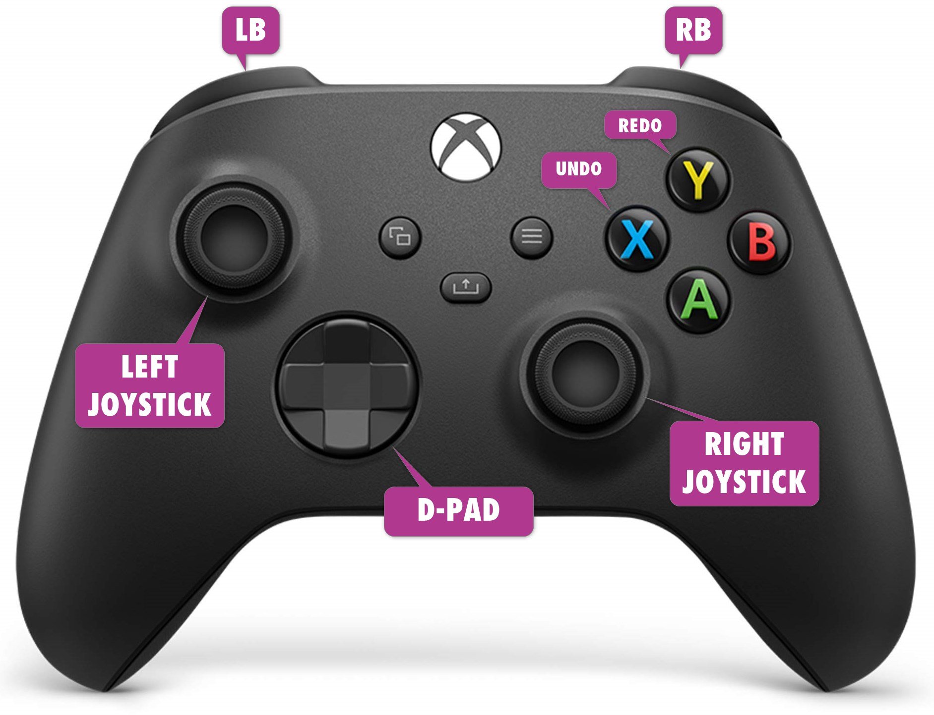
| Button | Action |
|---|---|
| LEFT JOYSTICK | Move the selected point dynamically in X/Y |
| D-PAD | Move the selected point exactly one pixel in X/Y |
| RIGHT JOYSTICK | Select next point in X/Y, this can be central point or bezier handles points |
| RB | If multiple Warp windows are open, jump to previously selected window |
| LB | If multiple Warp windows are open, jump to next selected window |
| X | Undo last step |
| Y | Redo last step |
NETWORK
PORTS
BASIC
| Process | port |
|---|---|
| RUNNER | 3018 |
| MANAGER | 3017 |
| DIRECTOR | 3021 |
| ASSET MANAGER | 3023 |
| OPERATIVE INTERNAL | 3020 |
EXTERNAL COMMUNICATION
| Process | port |
|---|---|
| OPERATIVE EXTERNAL | 3019 |
| LOKI | 3022 |
| OSC | 8000 |
| Art-Net (DMX) | 6454 |
| LEGACY PROTOCOL | 3039, 3040 |
MULTICAST DISCOVERY
| IP | 239, 2, 2, 2 |
| QUERY PORT | 3011 |
| RESPONSE PORT | 3012 |
HARDWARE RECOMMENDATIONS
There are recommendations for the computers running WATCHOUT Producer and WATCHOUT Manager to ensure smooth performance in show preparation and operation.
NOTE: The requirements will be updated continously.
PRODUCER
The computer running the Producer software should have the following minimum system requirements.
- Windows 10 or above
- WATCHOUT version 7 is a 64-bit application
- GPU required API is Vulkan 1.3
TESTED PRODUCER HARDWARE
Nvidia GPUs
- Pascal Quadro series and later AMD discrete GPUs
- AMD Radeon Pro Vii (driver: AMD software: Pro edition 23.Q1.1)
AMD integrated GPUs
- AMD RX Vega (AMD Ryzen 7 4700U)
- AMD Radeon Graphics (AMD Ryzen embedded V2718)
VISUAL RENDER
- Windows 10 or above
- WATCHOUT 7 is a 64-bit application
- GPU required API are openGL 4.4 / DirectX 11
TESTED VISUAL RENDERER HARDWARE
Nvidia GPUs
- Pascal Quadro series and later
WATCHPAX MEDIA SERVERS
The Dataton WATCHPAX range of servers are optimized for WATCHOUT playback. WATCHPAX 40, 42, 60 and 62 media servers can be upgraded to WATCHOUT version 7. WATCHPAX servers shipped from October 2023 will have the upgrade already applied.
The WATCHOUT version 7 upgrade for WATCHPAX 40, 42, 60, 62 servers is a license upgrade and a new image file will have to be installed. Please contact Dataton or your local Premium Partner for information on this process.
CUSTOM SERVERS
If you have an AMD graphics card, use Windows 10 as AMD has not released drivers for Windows 11, at the time of writing. If you intend to install and use Dante® then ensure there is no WIFI card, or disable any WIFI cards.
ASSET MANAGER
The Asset Manager should have a large, fast hard drive or multiple drives, as well as a GPU that supports Vulkan 1.3. This is where you store your media files which may be both large and numerous. As a rule of thumb, double up the amount of storage capacity you think you will need.
NETWORK
The computers running the Producer and Manager software must be connected using an ethernet network. A typical system has 1 Gigabit ethernet network ports on all computers and a high-quality ethernet switch with the required number of ports to connect the computers.
NOTE: A wireless network may work but is generally not recommended for reliability reasons and affects synchronization accuracy among display computers.
AUTOSTART
To setup WATCHOUT Manager to autostart on login, you can use the schtask.exe command. You need to run the command in a cmd-window with administrator privileges.
Click on the Windows logo, bottom left, and type cmd.exe, then select Run as administrator (see image below).
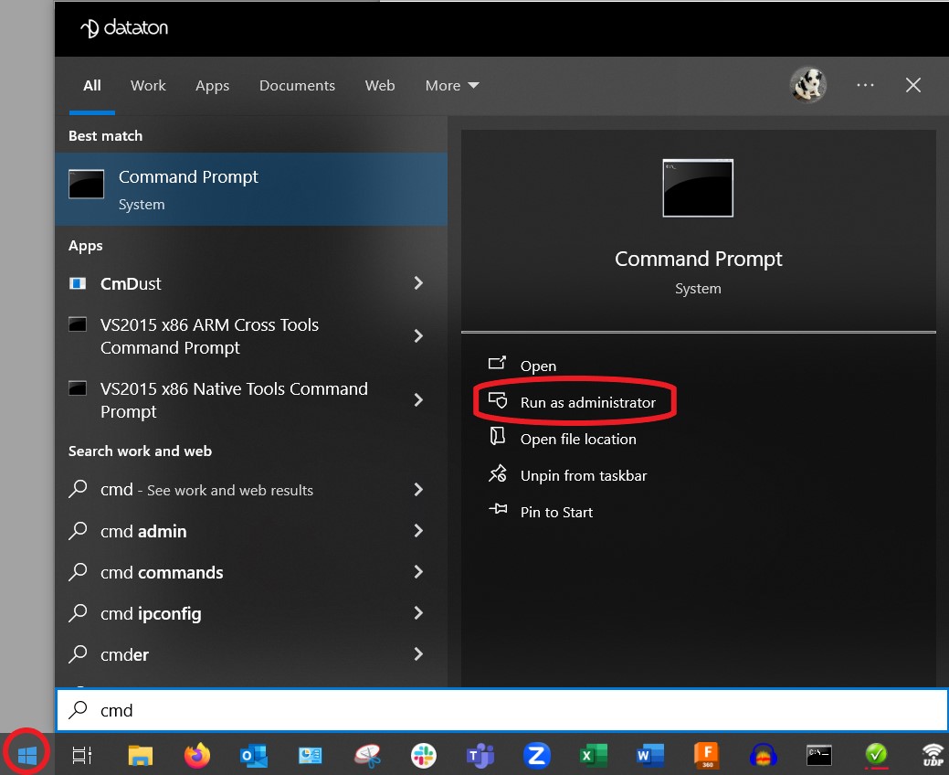
When the cmd-window is open, change directory to the WATCHOUT installation directory with the
cd C:\watchout7 command.
Type this line in the cmd-window:
schtasks.exe /create /tn "WATCHOUT manager" /xml c:\watchout7\wo-autostart.xml
If you have installed WATCHOUT in a different location than c:\watchout7, edit the xml file accordingly.
To edit scheduled tasks in more detail you can run the following command:
run taskschd.msc
The wo-autostart.xml file is located in the WATCHOUT installation folder.
SETTING UP YOUR SERVER
MAKE SURE THINGS ARE UP TO DATE
- Are you using the latest graphics driver?
- Are you using an up to date webview2?
- Have you installed Media Feature Pack (for N and KN versions of Windows 10)?
TIPS
On your display nodes you will benefit from:
- Running as few programs as possible.
- Turning off notifaction and popup programs.
- Turning off explorer (taskkill /im explorer.exe /f).
- Setting the priority of visual renderer (from task manager, or when starting or using wmic).
WATCHOUT 7 QUICKSTART GUIDE
INSTALLATION
WATCHOUT is Microsoft Windows-based software and is downloaded from Dataton website https://www.dataton.com/downloads
WATCHOUT can be installed on a Windows PC running Windows 10 and above. The software installation consists of:
- WATCHOUT Manager (contains Runner and Asset Manager)
- WATCHOUT Producer (contains Producer software)
To start using WATCHOUT it has to be first installed on every computer that will be used in your show. The installer is universal and will deploy both the producer components and the display server components.
Start the installation by double-clicking on the WATCHOUT 7 installer.
Please select all components you would like to use and specify the destination folder for the installation.
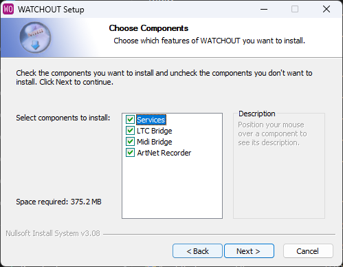
- Services: Contains all base functions.
- LTC Bridge: External app for LTC Input.
- MIDI Bridge: External app for MIDI input.
- ArtNet: External app for recording ArtNet universes.
STARTING UP
PRODUCTION SETUP
To start WATCHOUT Producer just find the shortcut on desktop or start it directly from the installation destination. Additional services (WATCHOUT Manager) will be started automatically.
C:\WATCHOUT7\bin\Producer.exe
Note: The Producer has to be run with Windows administrator privileges.
DISPLAY SETUP
To start WATCHOUT on the display server just find WATCHOUT Manager shortcut on desktop after installation.
C:\WATCHOUT7\process-manager.exe
Note: The Manager has to be run with Windows administrator privileges.
On a computer that will be used as a display server, video rendering will start automatically after the display is added to a show and enabled.
SHOW DEPLOYMENT
The entire show is programmed from the Producer software, there is no setup or configuration required on the display end, other that it has to be running and accessible on the network.
SETTING UP A NEW SHOW
Start the Producer and select the New Show option on the welcome screen.
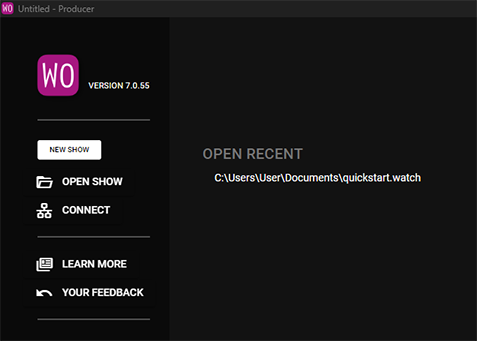
Every WATCHOUT show requires a Director which will maintain current show, version handling and propagation of changes to all connected display servers. By default the Director role will be assigned to a local host (the same machine that is running Producer). Current Director and Asset Manager assignments are indicated in the top right of the menu bar.
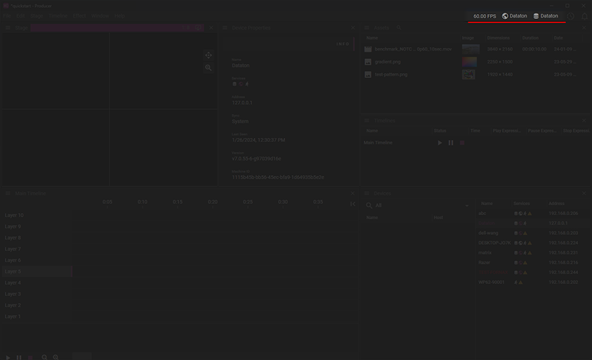
To assign Director and Asset Manager roles to a different host, find the desired WATCHOUT node in the Devices list and assign the role from the context menu (right-click).
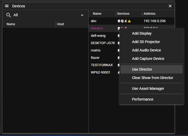
Displays can be added by selecting the desired node in Devices.
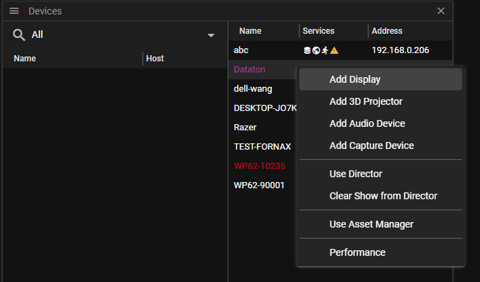
Or directly from Stage.
To correctly address the display, select the desired node from the dropdown list and hit the enable button (heart).
To help identify the display, render information can be used. This will show the name of display along with most important properties.
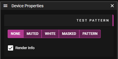
At this point the show is live and any content added to the Stage will be sent to display servers and immediately rendered.
HANDLING MEDIA
- Add media
- Optimizing explanation
- Add assets to show
- See asset on display
SUMMARY
- General tips