Hardware Sync
Configure hardware synchronization between multiple WATCHPAX 64 units using the NVIDIA Quadro Sync II card.
Hardware sync ensures that all GPU outputs across multiple WATCHPAX 64 units refresh at exactly the same time, eliminating visible tearing or frame offset between displays. This is essential in multi-server video wall setups where content spans across outputs driven by different machines -- without hardware sync, each GPU runs on its own internal clock and frames will drift apart over time, causing noticeable visual seams. The NVIDIA Quadro Sync II card connects the units via dedicated sync cables and designates one output as the timing source that all others lock to.
Physical Setup
Before configuring the sync settings, make sure the servers are correctly connected together.
- Use CAT6 or better cables for sync connections. These carry sync data only — do not connect them to a network switch, router, or network jack.
- Status LEDs on Quadro Sync cards should be active (either orange or green color).
- Cable length should be short and of high signal integrity.
- Do not make signal loops. This is a linear chain.
- Either of the two RJ45 ports on the Quadro Sync II card can be used when chaining units together (see connectors 14 and 15 in Connectors).
The sync signal should be structured in the following manner, with the signal source in the middle of the cluster:
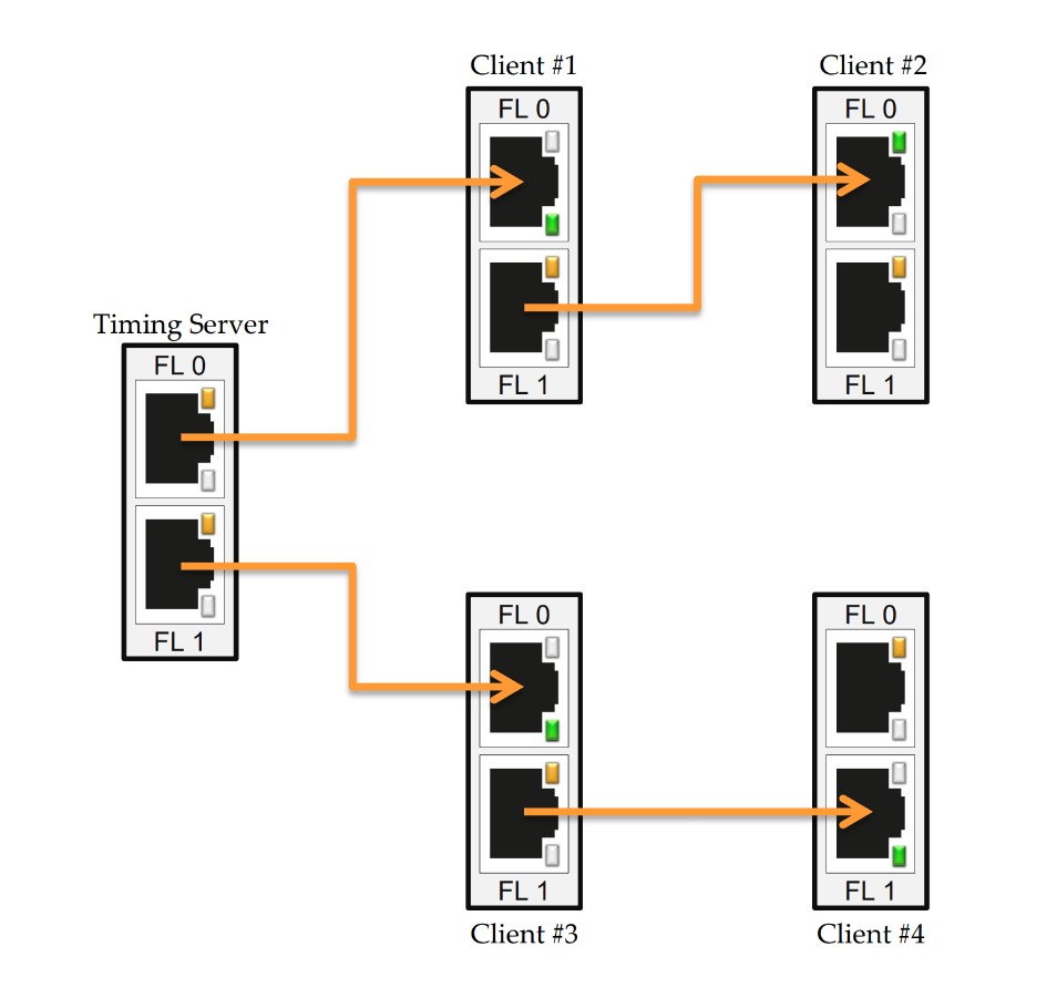
This way, the distance that the signal needs to travel is cut down, which provides a more stable signal.
Configuring Sync Settings
Follow the steps below to configure hardware synchronization across your WATCHPAX 64 cluster. Start with the unit that will serve as the timing source, then repeat the client steps on all remaining units.
In WATCHPAX Config, select the Setup Sync option from the toolbar. This opens the Configure Hardware Sync window where you can assign timing roles to each display output. You must configure sync settings on each WATCHPAX 64 unit individually -- start with the unit that will act as the timing source before moving to the client units.
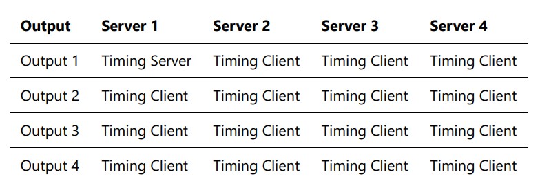
Set up the machine that includes the timing server first. Only one output on one server can become the timing source -- all other outputs across all units should be set up as clients.
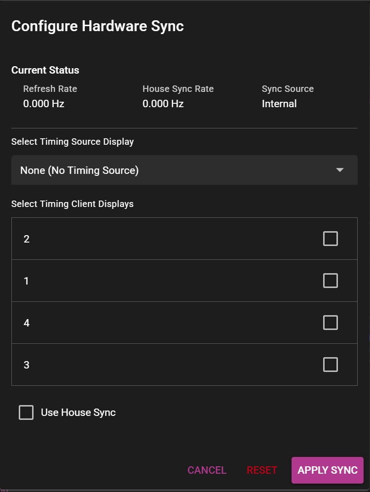
Click Apply Sync to write the synchronization configuration to the hardware. Wait for a confirmation message to appear indicating that the settings were applied successfully. If the confirmation does not appear, verify that the physical cabling is correct and that the Quadro Sync card LEDs are active. Repeat the configuration process on each remaining WATCHPAX 64 unit in the cluster, setting all their outputs as clients.
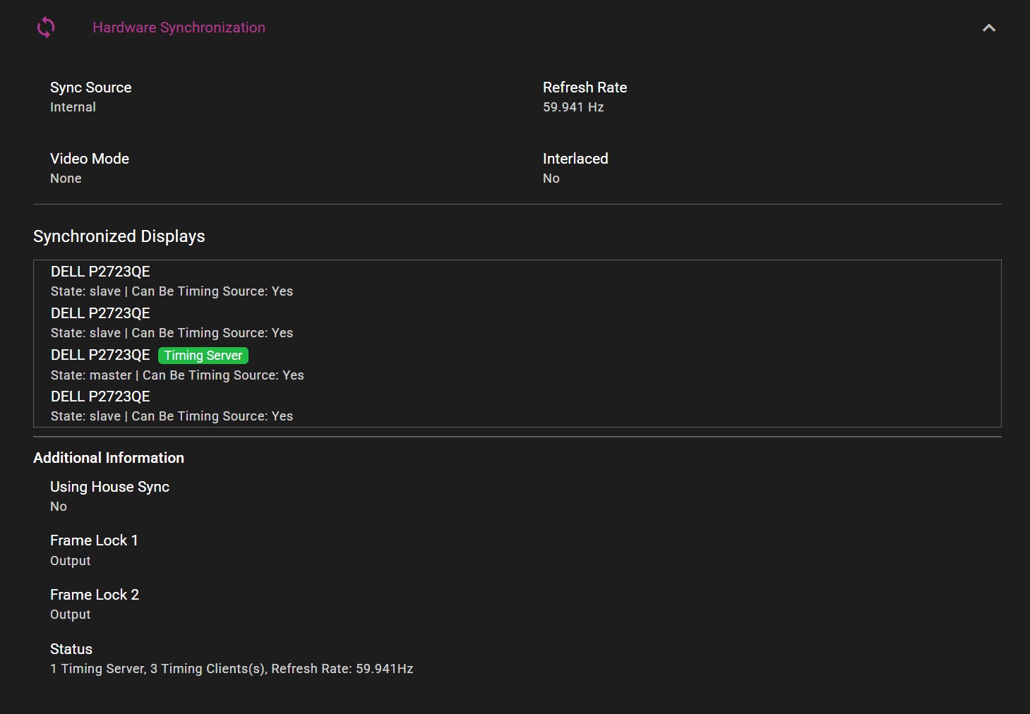
After all units have been configured, you can verify the sync status. The diagram below shows a typical setup for a 4-server cluster. The current sync configuration for each unit can be viewed in the Hardware Synchronization section of WATCHPAX Config. Confirm that one output shows as the timing source and all others show as clients with a locked status.