TABLE OF CONTENTS
WATCHPAX CONFIG
-
INTRODUCTION
TABLE OF CONTENT
INTRODUCTION TO WATCHPAX CONFIG
WATCHPAX Config is a web-based tool, developed for the purpose of making configurations on your WATCHPAX media server over a network. This way there is no need to have a keyboard, mouse and display screen connected to your WATCHPAX server in order to change EDID, set up Mosaic configurations or use hardware synchronization. All of this can be done from your production computer (the one running WATCHOUT Producer).
WATCHPAX MODELS
Below is a list of WATCHPAX models currently able to utilize the WATCHPAX Config tool:
- WATCHPAX 30
- WATCHPAX 40/42
- WATCHPAX 60*/62/64 >* Currently, WATCHPAX Config only supports capture cards from Deltacast. Therefore the Datapath capture cards in WATCHPAX 60A and 60B will not appear in the tool.
ACCESSING WATCHPAX CONFIG
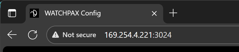
The WATCHPAX Config tool is accessed through a web browser. Keep in mind that the WATCHPAX server and the computer accessing it have to be on the same network, although internet access is not required. Enter the IP address of the WATCHPAX server into the web browsers search field, followed by the port number :3024, as in the following example:
Example: 169.254.4.221:3024
A user interface will be displayed, showing information about all connected outputs. Read more in the Interface chapter.
INTERFACE
TABLE OF CONTENT
LAYOUT AND FUNCTIONALITY
Below is an example of how the WATCHPAX Config user interface looks when connected to a WATCHPAX 64:
Note: The WATCHPAX 64 model is our server machine with the largest amount of possible hardware variations, and thus the most functionality visible in the user interface. That is why it has been used in this example. Other server models may not have all of the options or graphical elements shown below.
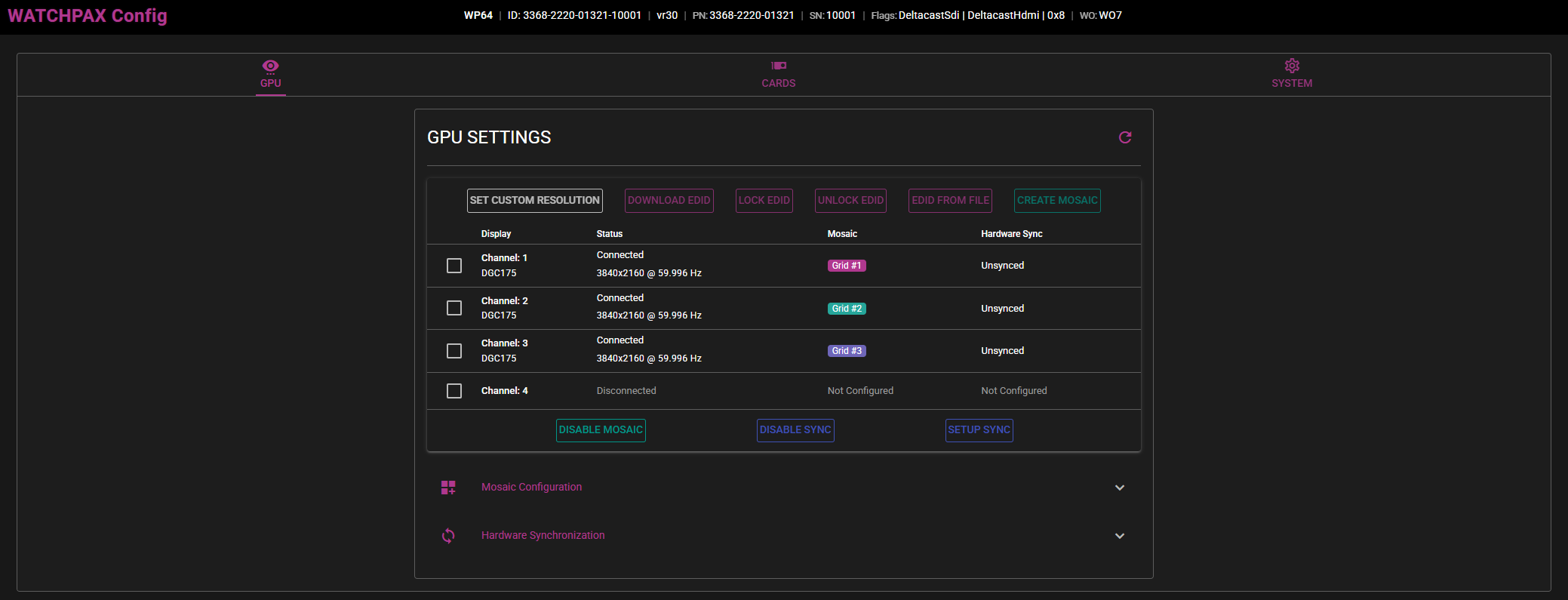 User interface layout.
  Information displayed in order from left to right: Model name, machine ID, image version, product number, serial number, flags for different hardware components, WATCHOUT versions.
TABS
The graphical user interface consists of selectable tabs in the upper row. Each tab with different information being displayed and settings to configure.
GPU
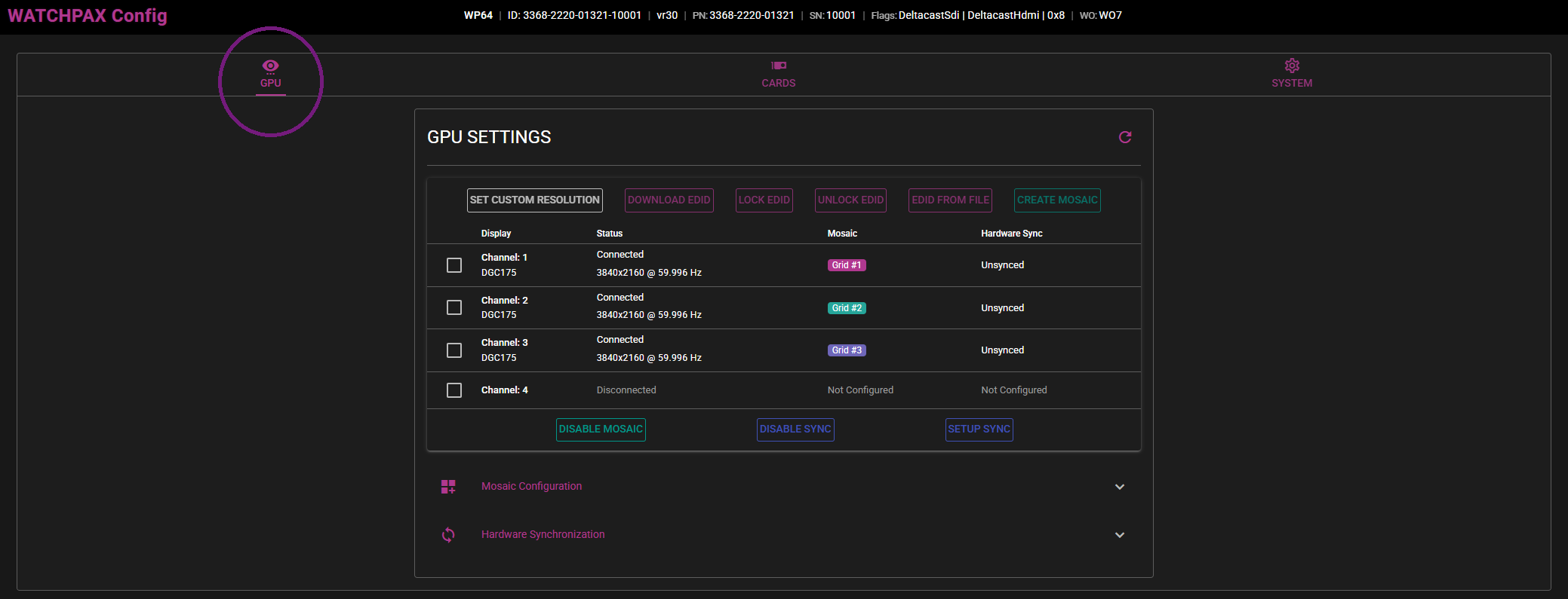
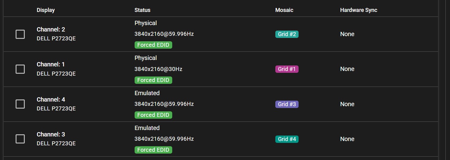
With the GPU tab selected, an overview of the displays connected to the server's GPU outputs is shown. Here you can see information like:
- What display is connected to what channel,
- Model name of that display,
- If the display has an EDID configured,
- Resolution and refresh rate per display,
- If the display is part of a Mosaic grid,
- If hardware synchronization is enabled on the display.
In this view, there are several settings that can be configured on the server. These are EDID, Mosaic and Hardware synchronization. They will be explained in their own separate chapters.
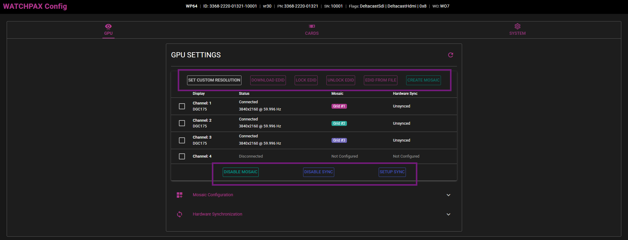
Also in the GPU tab, there are dropdown menus showing more information about their respective areas.
MOSAIC CONFIGURATION
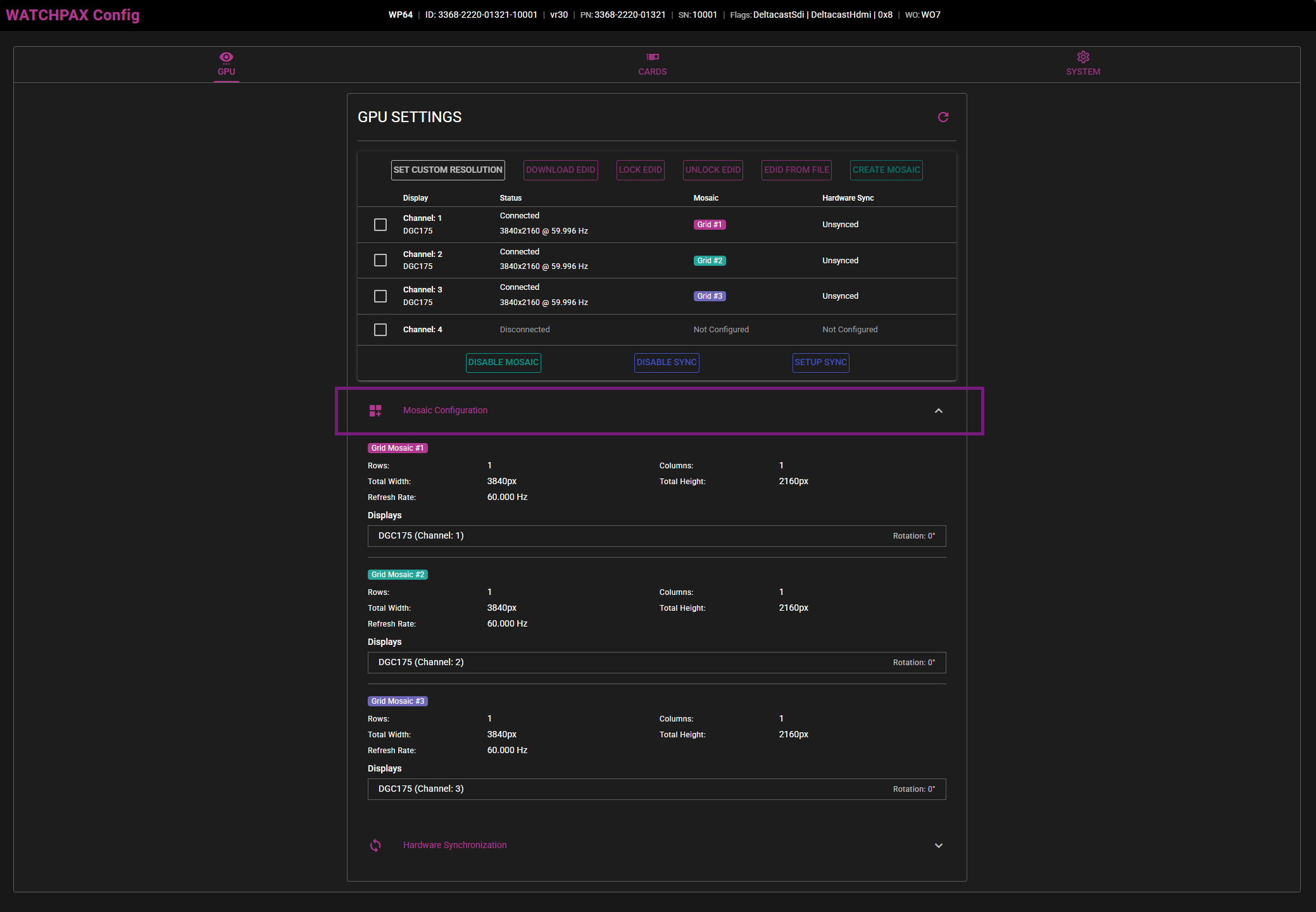
If you have one or more Mosaic grids set up, information about them will be shown here. This will be information like amount of rows and columns, resolution, as well as if displays are on the same grid or on separate grids.
HARDWARE SYNCHRONIZATION
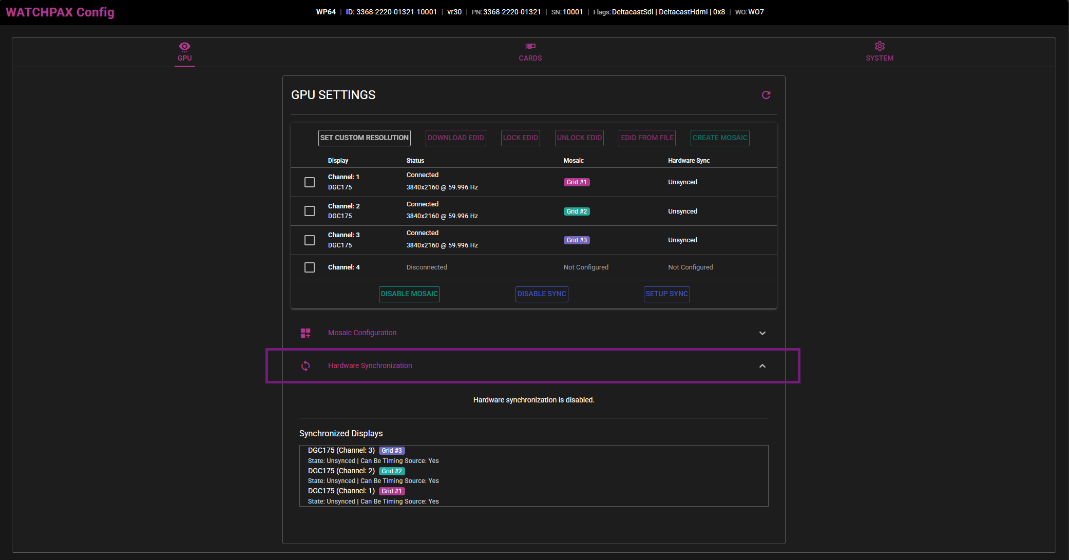
Whether or not hardware synchronization is enabled and what displays are synchronized will be shown under this dropdown menu.
CARDS
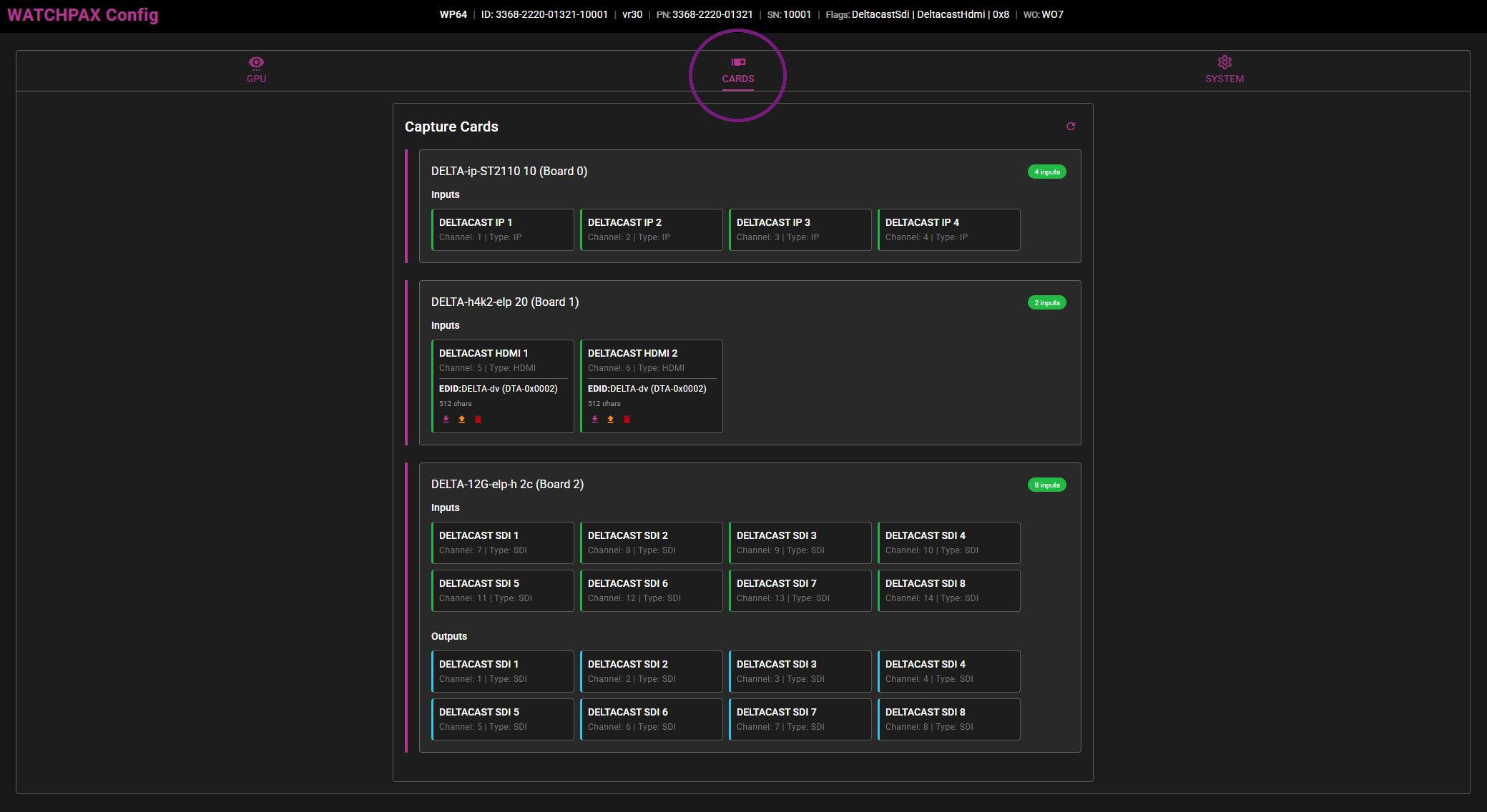
With the CARDS tab selected, an overview of all the different capture cards installed on the motherboard of the WATCHPAX will be displayed, as well as their active inputs and outputs (SDI). In this case there is an ST2110 ip capture card, an HDMI capture card and an SDI capture card from Deltacast installed.
Note: Currently, WATCHPAX Config only supports cards from Deltacast, which means that the Datapath capture cards in the WATCHPAX 60A and 60B will not show up in this overview.
SYSTEM
NETWORK
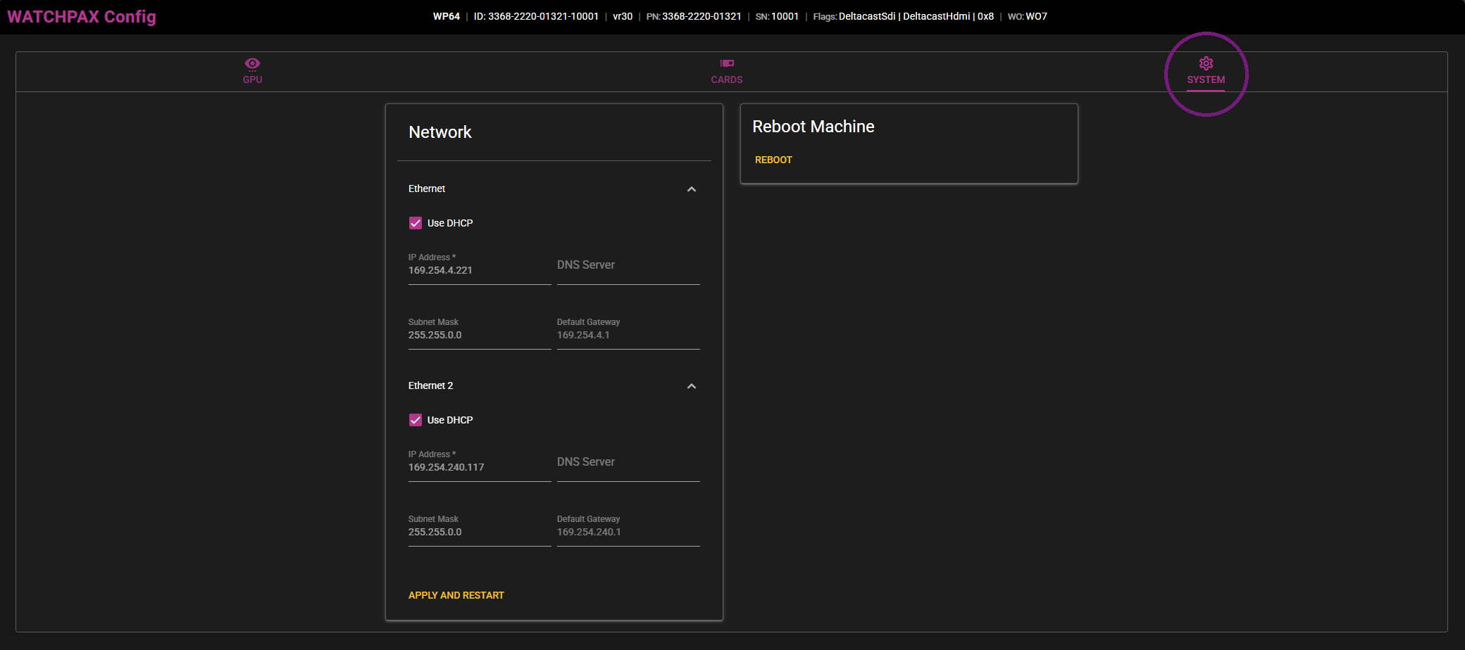
Under the SYSTEM tab there is information about network connections on the WATCHPAX. Here it is possible to change network settings and use a static IP address. In that case, uncheck Use DHCP on the network connection you want to change. Both ethernet and wireless connections will appear here. Enter the desired IP address, DNS server, subnet mask and default gateway and click on Apply and restart. The WATCHPAX will then reboot itself with the new network settings in use.
If static IP has previously been set, simply checking the Use DHCP option followed by Apply and restart will reassign an automatic IP address to the server on bootup.
REBOOT MACHINE
There is also an option on the righthand side for a simple reboot of the machine remotely if needed.
EDID
SETTING UP EDID EMULATION
Under the GPU tab of the user interface there is the possibility to set up EDID on all of the displays connected to the graphics card. Below are the steps to setting this up:
- Download the EDID from a display.
Select the display in the list and choose the Download EDID option.
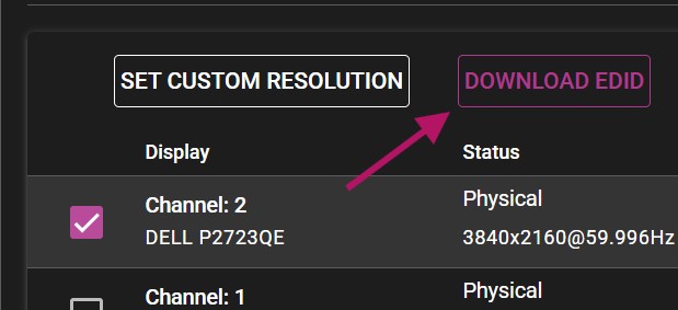
NOTE: The web browser may consider the downloaded file insecure and might require additional actions to approve it.
- Select all displays (or however many displays you want to have the EDID on) and choose EDID FROM FILE.
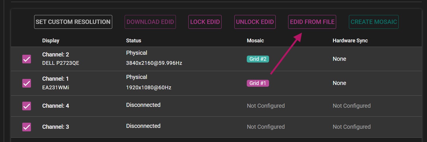
A new menu will appear, allowing you to upload the previously downloaded EDID to all display channels. Browse to the downloaded file, or simply drag and drop the file into the window.
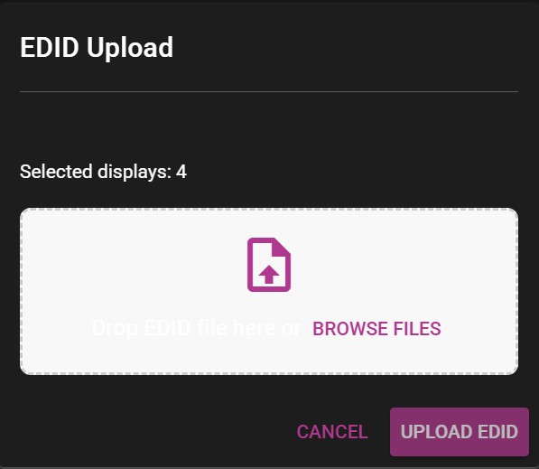
After uploaded the EDID, all channels previously selected will show the Forced EDID label under their status.
MOSAIC
ENABLING MOSAIC
Under the GPU tab is the possibility to set up one or more Mosaic grids, using the displays connected to the WATCHPAX.
IMPORTANT Before beginning, make sure all displays have the ability to use a desired display mode (resolution + refresh rate)
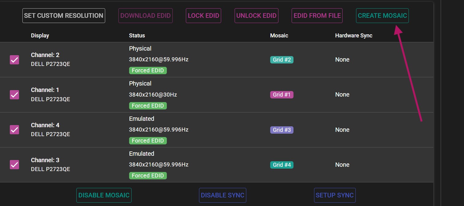
- Select all displays and click on the CREATE MOSAIC option. If there is only one display present or only one display selected, the option will be grayed out.
- In the Create Mosaic Grid menu, configure the grid to specification.
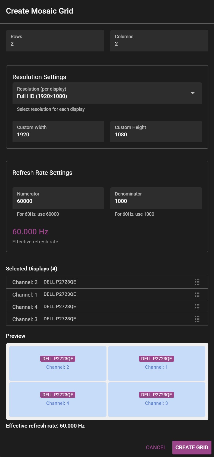 Example of the Create Mosaic Grid window.
-
Select the appropriate number of rows and columns. >For 2x2 setup, the number of columns and rows will be 2 each. >For 4 displays stacked horizontally (panorama), the grid would consist of 1 row and 4 columns (1x4).
-
Select the resolution (for each display) by specifying width and height. >The resolution is specified for each participating display, not the whole resulting mosaic. >For example: To get a 4K mosaic from 4 HD outputs, you would put 1920x1080 in Custom Width and Custom Height respectively.
-
Select desired refresh rate.
NOTE: For 59.94 Hz the correct values are 60000 for Numerator and 1001 for Denominator.
- Drag the correct channels to their respective positions in the preview panel to create the desired layout.
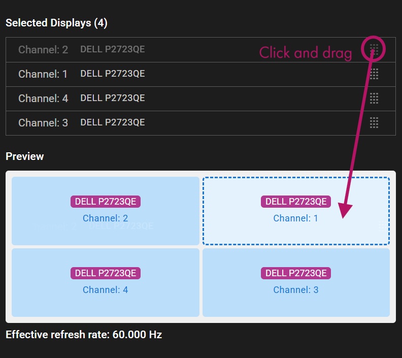
- Click Create Grid to apply changes.
NOTE: Before finalizing the mosaic grid, make sure WATCHOUT is not rendering on the displays that are being used for the grid. Disable all of them before accepting changes.
- If everything was set up correctly, a message will confirm that the mosaic grid was created successfully.

NOTE: In the case of using mosaic clusters with several WATCHPAX units, each server must be set up separately.
SYNCHRONIZATION
TABLE OF CONTENT
IMPORTANT: Hardware synchronization functions will only work if the system is set up in the correct sequence, as below.
- EDID emulation needs to be handled first.
- Mosaic grid should follow.
- Hardware sync is the last one to be enabled.
HARDWARE SYNC
Follow the steps below to set up hardware synchronization in the WATCHPAX Config user interface.
- Under the GPU tab, use the SETUP SYNC option to configure the hardware sync settings.
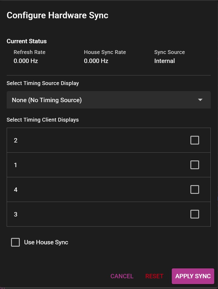
A new menu window will appear, allowing you make the desired changes to the settings.
-
Under Select Timing Source Display, select the display that will serve as the timing source.
-
Check the boxes on all remaining displays as clients.
-
Click Apply sync and wait for a confirmation message.

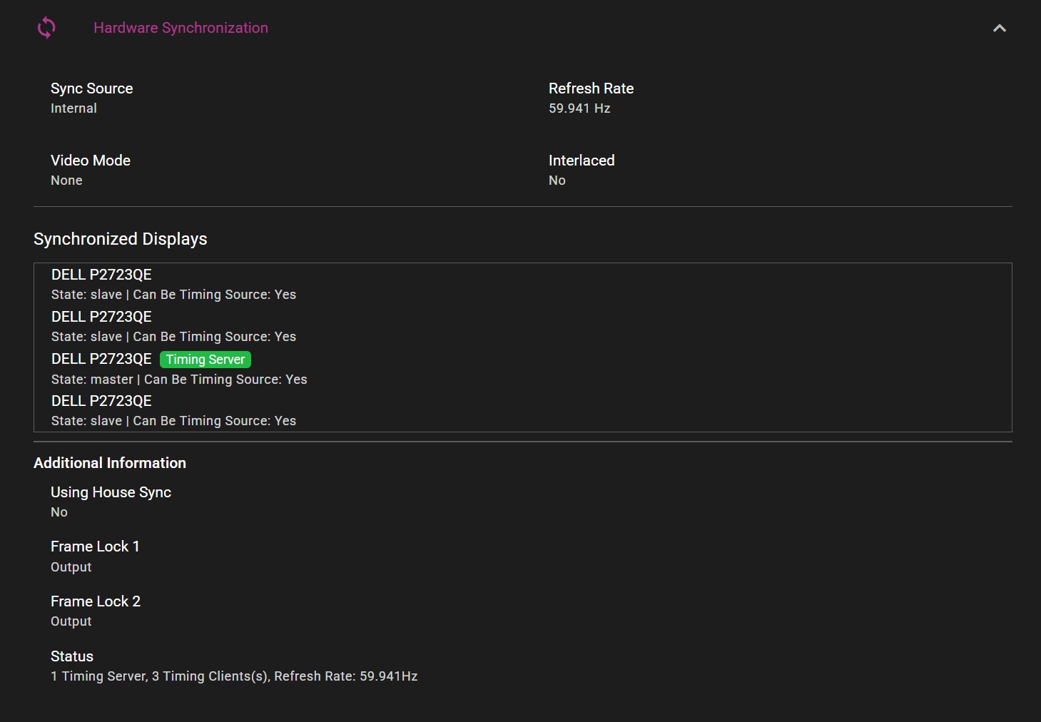
Current sync configuration can be viewed in the Hardware Synchronization section under the GPU tab:
HOUSE SYNC
In the Configure Hardware Sync window there is also an option to enable House Sync, which allows the server to receive a synchronization signal from an outside source, through the BNC connector on the sync card.
SYNCHRONIZATION USING MULTIPLE SERVERS
The following section has information about setting up hardware synchronization between several WATCHPAX servers with built-in sync cards.
Before configuring the sync settings, make sure the servers are correctly connected together.
- Use CAT6 or better ethernet cables.
- Status LEDs on Quadro Sync cards should be active (either orange or green color).
- Cable length should be short and of high signal integrity.
- Do not make signal loops. This is a linear chain.
- It is possible to use either of the two ethernet ports on the card when connecting the units with a cable.
The sync signal should be structured in the following manner, with the signal source in the middle of the cluster:
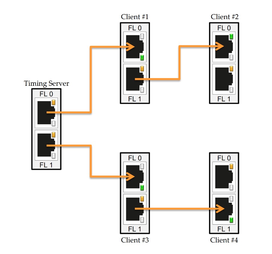
This way, the distance that the signal needs to travel is cut down, which provides a more stable signal.
- Use the SETUP SYNC option to create the hardware sync settings.
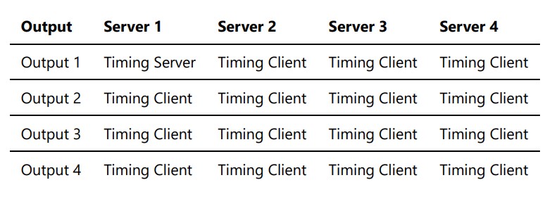
NOTE: In the case of using hardware sync across multiple WATCHPAX servers, set up the machine that includes the timing server first. Only one output on one server can become the timing source, all other outputs should be set up as clients.
-
On the server that will serve as the signal source, select the timing source display. Skip this step on the rest of the servers.
-
Select all remaining displays as clients.
-
Click Apply sync and wait for a confirmation message.
Typical setup for four servers with four displays each: