SYNCHRONIZATION
TABLE OF CONTENT
The WATCHPAX 64 can optionally be equipped with a NVIDIA Quadro Sync II card, which enables some useful functionalities. These include synchronizing mosaic groups spanning several GPUs, frame locking, synchronization to an external timing source as well as outputting an internal timing source.
Below are instructions on how to access these features from within the WATCHPAX Config network-based user interface.
ACCESSING WATCHPAX CONFIG
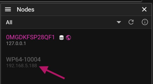
Start by finding the IP address of the WATCHPAX 64. It should show on the WATCHOUT splash screen, but if that is unavailable, the IP address can also be found in the Nodes window in the Producer software on the production computer. The WATCHPAX name will be displayed, with its IP address right below it.
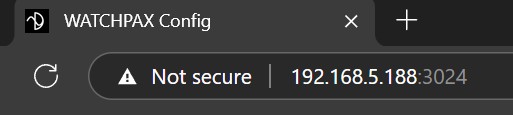
Open up a web browser and visit the server address with port 3024. The WATCHPAX 64 and the production computer both need to be on the same network for WATCHPAX Config to be accessed.
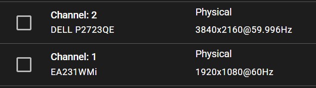
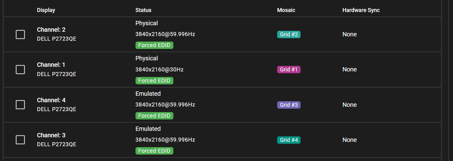
A user interface will be displayed, showing information about all connected outputs.
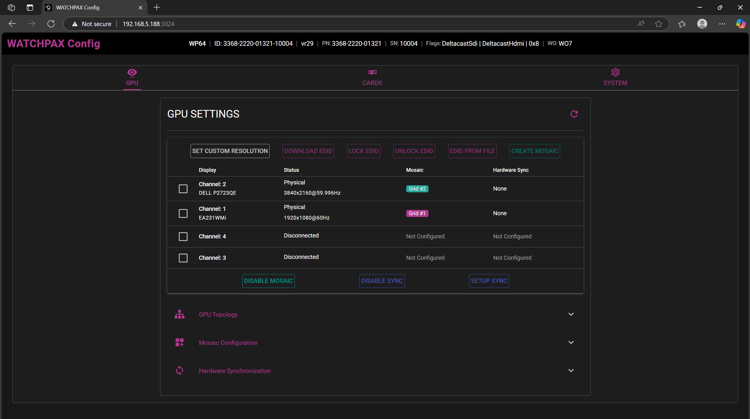
All channels should show a display connected under the 'Channel' label, as well as the current resolution and refresh rate.
NOTE: In the case of using mosaic clusters with several WATCHPAX units, each server must be set up separately.
IMPORTANT: Hardware synchronization functions will only work if the system is set up in the correct sequence, as below.
- EDID emulation needs to be handled first.
- Mosaic grid should follow.
- Hardware sync is the last one to be enabled.
SETTING UP EDID EMULATION
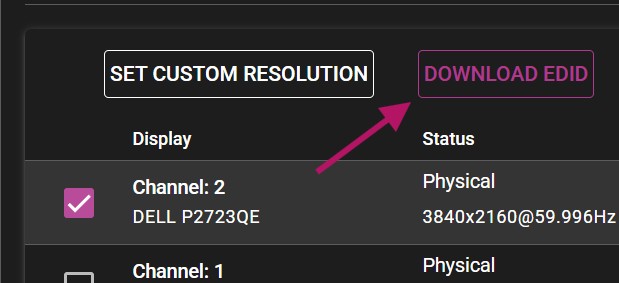
- Download the EDID from a display.
Select the display in the list and choose the Download EDID option.
NOTE: The web browser may consider the downloaded file insecure and might require additional actions to approve it.
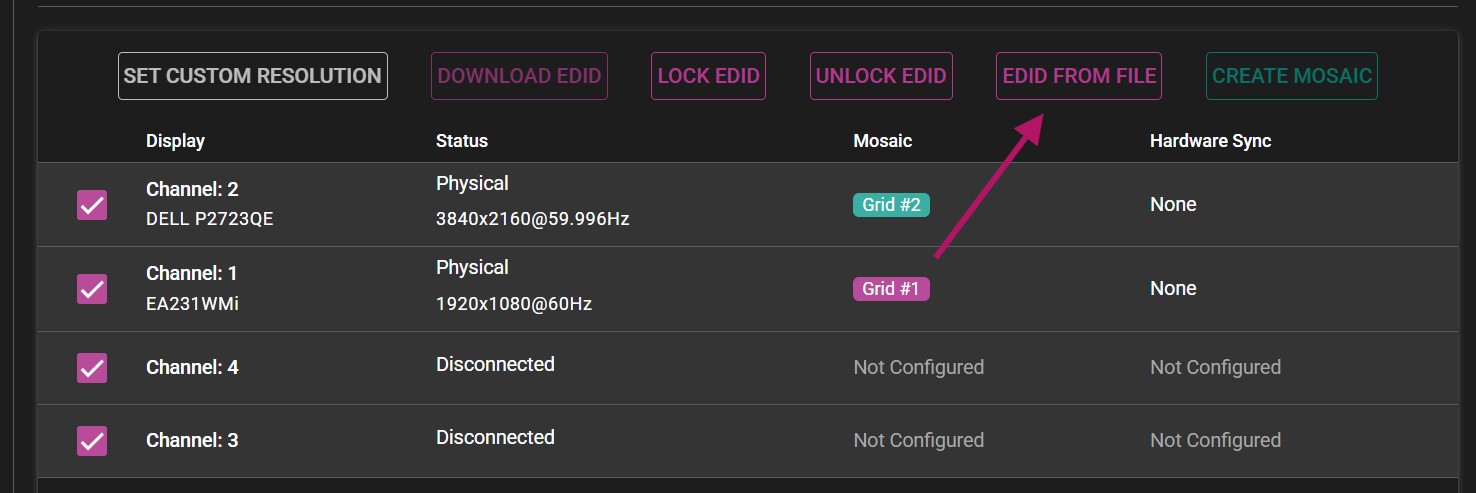
- Select all displays and choose EDID FROM FILE.
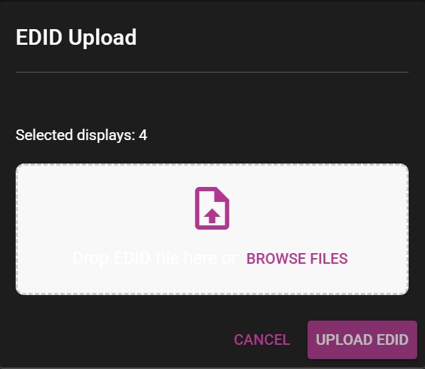
A new menu will appear, allowing you to upload the previously downloaded EDID to all display channels. Browse to the downloaded file.
After uploaded the EDID, all channels should show the Forced EDID label under their status.
ENABLING MOSAIC
IMPORTANT Before beginning, make sure all displays have the ability to use a desired display mode (resolution + refresh rate)
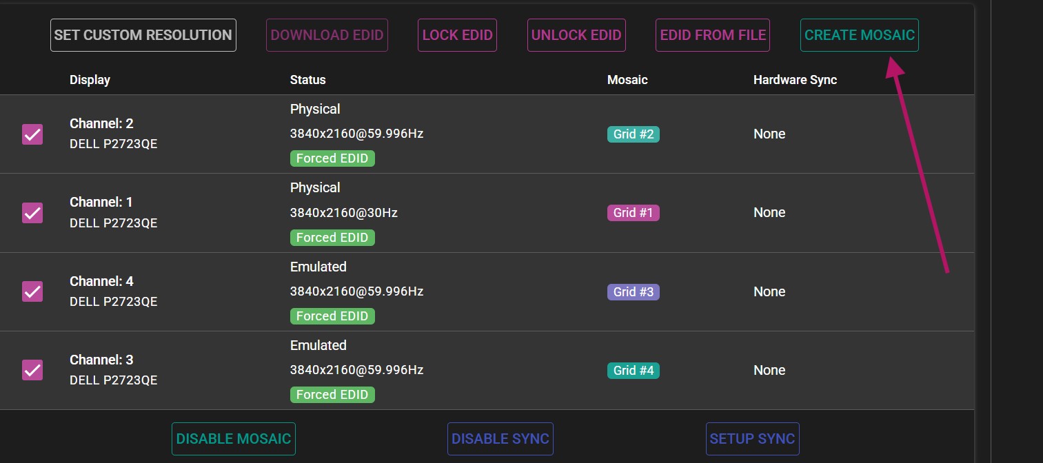
- Select all displays and select the CREATE MOSAIC option. If there is only one display present or only one display selected, the option will be grayed out.
- In the Create Mosaic Grid menu, configure the grid to specification.
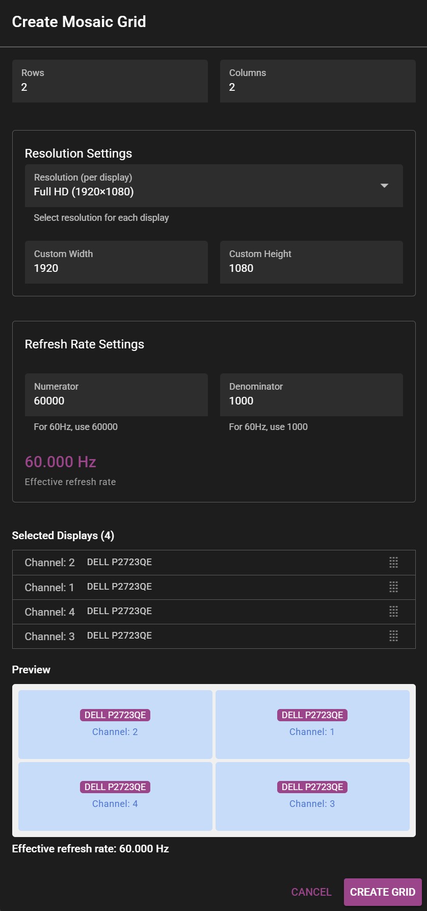 Example of the Create Mosaic Grid window.
-
Select the appropriate number of rows and columns. >For 2x2 setup, the number of columns and rows will be 2 each. >For 4 displays stacked horizontally (panorama), the grid would consist of 1 row and 4 columns (1x4).
-
Select the resolution (for each display) by specifying width and height. >The resolution is specified for each participating display, not the whole resulting mosaic. >For example: To get a 4K mosaic from 4 HD outputs, you would put 1920x1080 in Custom Width and Custom Height respectively.
-
Select desired refresh rate.
NOTE: For 59.94 Hz the correct values are 60000 for Numerator and 1001 for Denominator.
- Drag the correct channels to their respective positions in the preview panel to create the desired layout.
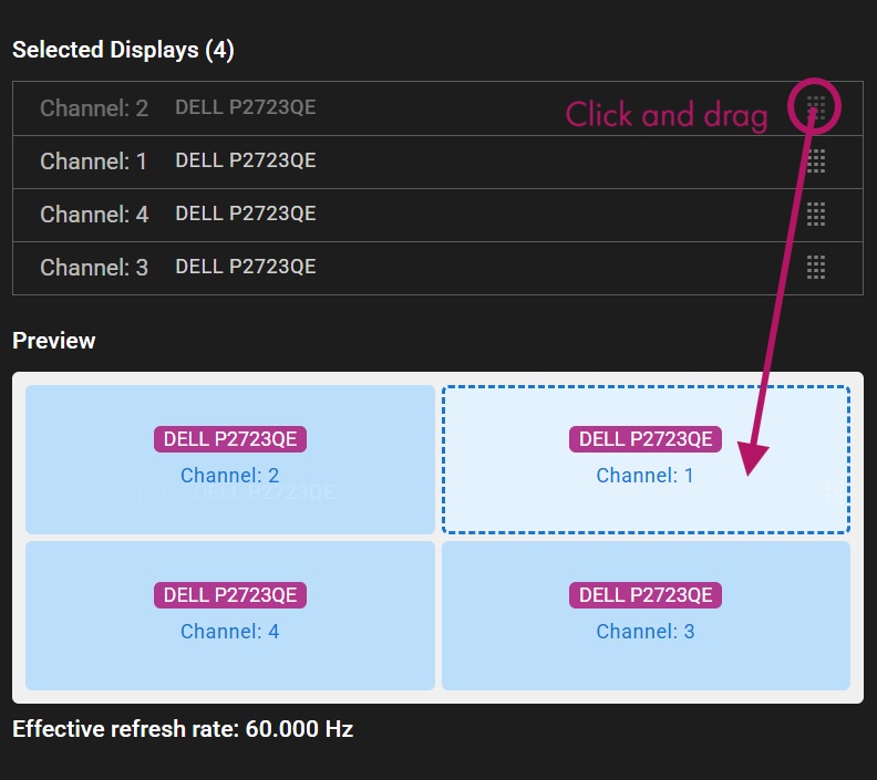
- Click Create Grid to apply changes.
NOTE: Before finalizing the mosaic grid, make sure WATCHOUT is not rendering on the displays that are being used for the grid. Disable all of them before accepting changes.
- If everything was set up correctly, a message will confirm that the mosaic grid was created successfully.

HARDWARE SYNC
PHYSICAL SETUP
Before configuring the sync settings, make sure the servers are correctly connected together.
- Use CAT6 or better ethernet cables.
- Status LEDs on Quadro Sync cards should be active (either orange or green color).
- Cable length should be short and of high signal integrity.
- Do not make signal loops. This is a linear chain.
- It is possible to use either of the two ethernet ports on the card when connecting the units with a cable.
The sync signal should be structured in the following manner, with the signal source in the middle of the cluster:
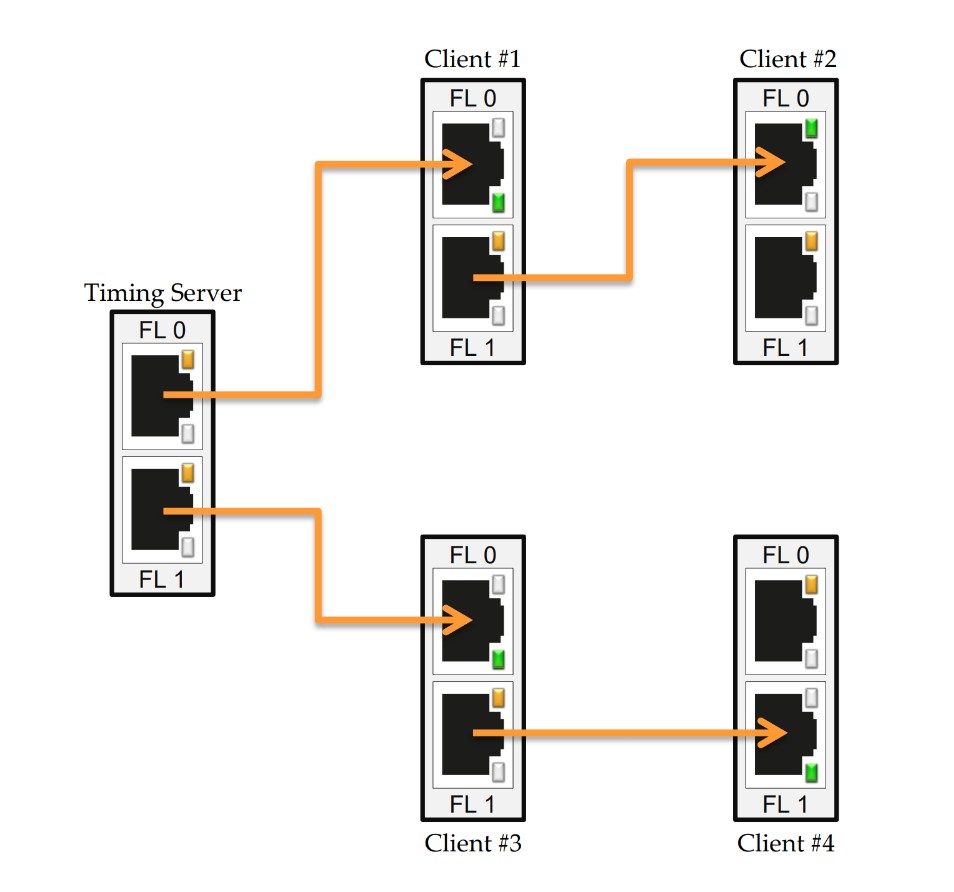
This way, the distance that the signal needs to travel is cut down, which provides a more stable signal.
- Use the SETUP SYNC option to create the hardware sync settings.
NOTE: Set up the machine that includes the timing server first. Only one output on one server can become the timing source, all other outputs should be set up as clients.
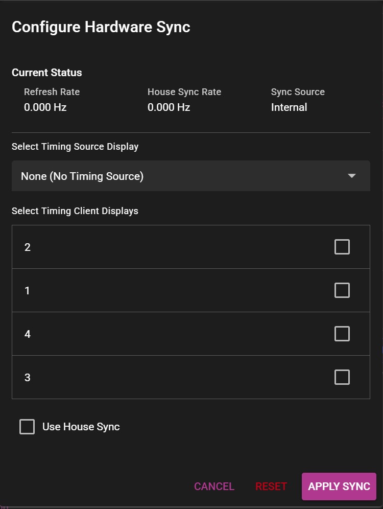 Example of the Configure Hardware Sync window.
-
On the server that will serve as the signal source, select the timing source display. Skip this step on the rest of the servers.
-
Select all remaining displays as clients.
-
Click Apply sync and wait for a confirmation message.

Typical setup for 4 display servers:
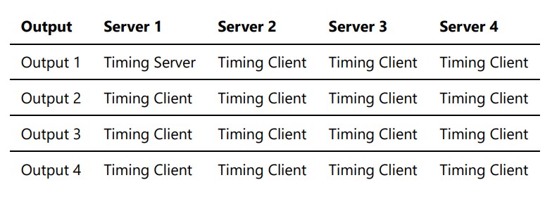
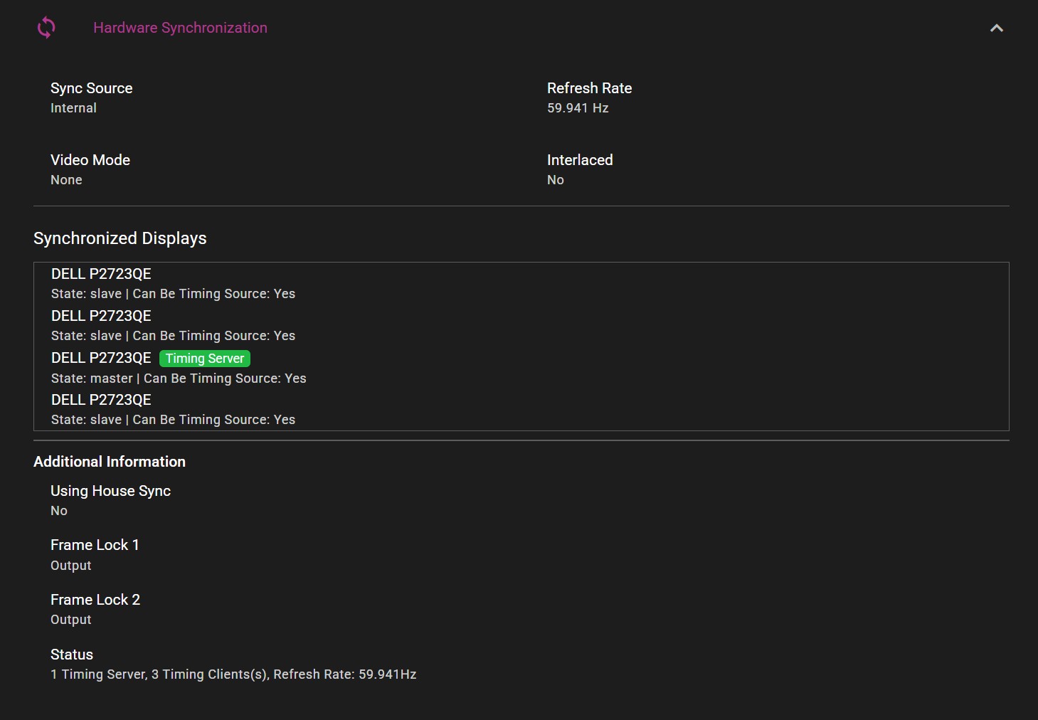
Current sync configuration can be viewed in the Hardware Synchronization section: