DATATON WATCHPAX 64
USER'S GUIDE
PREFACE
© Copyright 2025 DATATON AB (“Dataton”). All rights reserved.
Dataton, the Dataton logo, WATCHOUT and WATCHPAX are registered trademarks of DATATON AB. All other company and product names are trademarks or registered trademarks of their respective owners. Use of a term in this publication should not be regarded as affecting the validity of any trademark.
Dante is a registered trademark of Audinate Pty Ltd.
NOTCH is a registered trademark of 10 bit FX.
The information in this guide has been carefully checked and is believed to be accurate.
However, Dataton assumes no responsibility for any inaccuracies or errors in this manual or the products described. In no event will Dataton be liable for direct, indirect, special, incidental, or consequential damages resulting from any defect or omission in this manual, even if advised of the possibility of such damages. The technical information contained herein regarding features and specifications is subject to change without notice. Products or manufacturers mentioned do not constitute a recommendation or endorsement by Dataton.
User forum https://forum.dataton.com
Knowledge Base https://knowledge.dataton.com/knowledge
If you have an issue and need to contact the support department, please visit the Help Center and submit a support ticket. https://www.dataton.com/helpcenter
Document version: 3799 2.0
TABLE OF CONTENTS
-
Warranty, Conformity and Disposal
INTRODUCTION
TABLE OF CONTENT
INTRODUCTION TO WATCHPAX 64
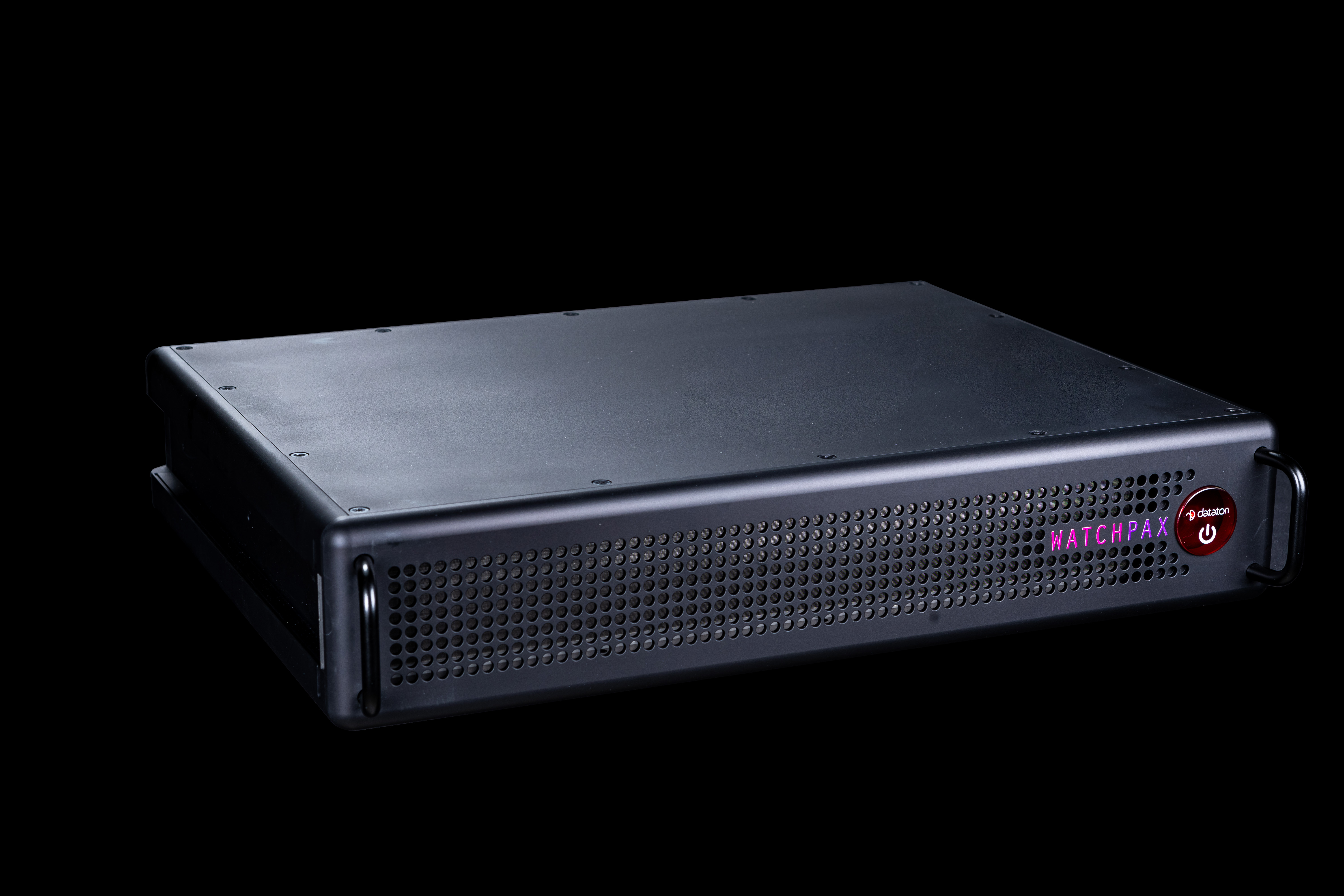
WATCHPAX 64 is a dedicated media server for use with Dataton WATCHOUT. Each unit has a built-in WATCHOUT license and a strong standard specification. In addition, the WATCHPAX 64 offers configuration options on three slots for ST2110, SDI, HDMI, as well as optional sync and SSD size on order.
The WATCHPAX 64 gives you all the advantages of Dataton’s range of dedicated locked-down media servers with the benefits of a configurable unit. Designed to make your WATCHOUT shows shine, the WATCHPAX 64 is a stylish and robust aluminium unit manufactured to a high quality specification. You choose the slot configuration on order, tailoring the unit to your needs. And if those needs change further down the line, there’s also the possibility of revising those options.
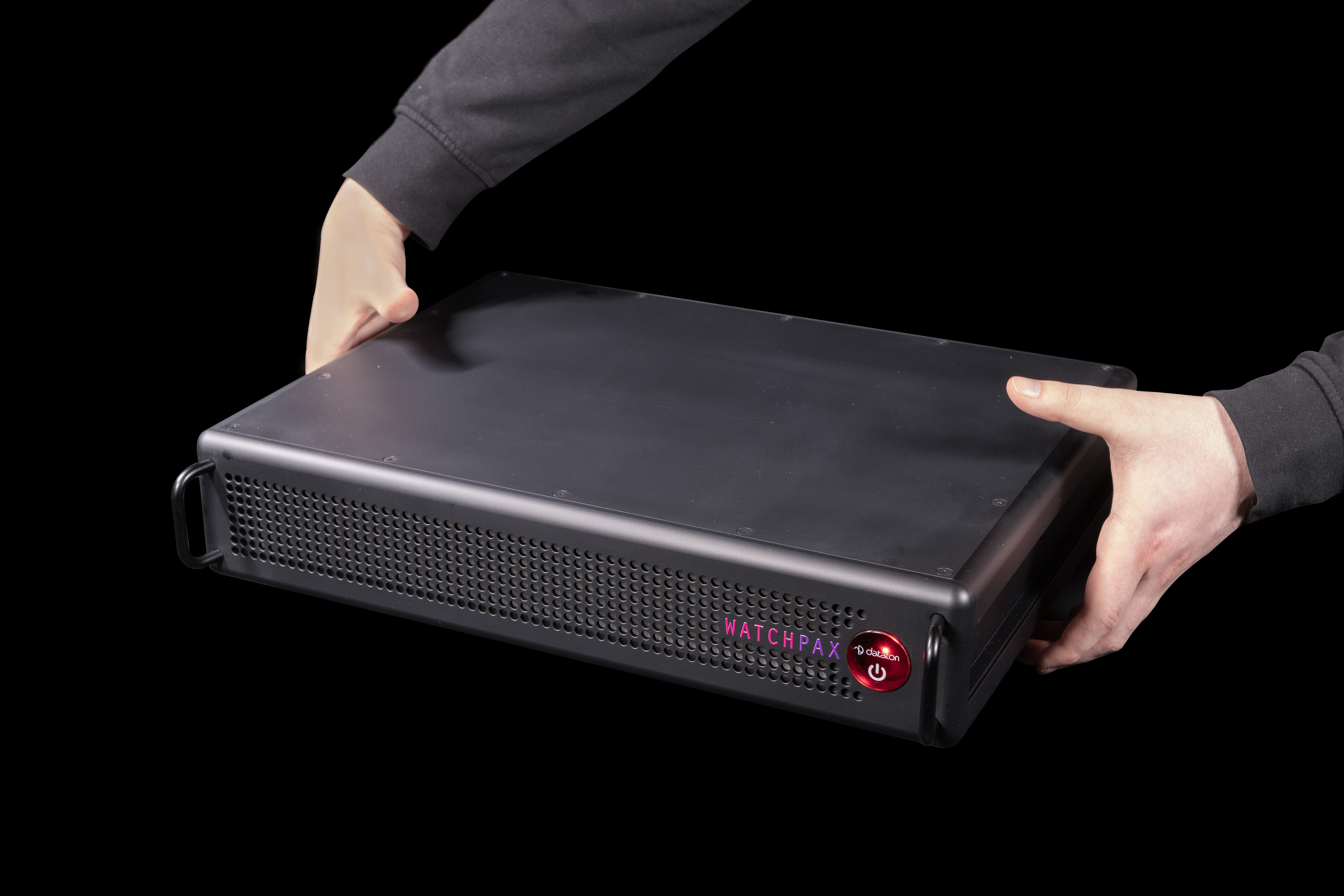 Size reference.
ACCESSORIES
Included:
- 1 x IEC 60320 10A/250V AC power cord with C13 connector
- 4 x DisplayPort 1.4 to HDMI 2.0b adapters
- Rubber feet
- With SDI capture card option: 9x Micro BNC to BNC adapters
Available separately:
- Kit for mounting in 19-inch rack
- Micro BNC to BNC adapters
- DisplayPort 1.4 to HDMI 2.0b adapters
DIMENSIONS
- Width 446 mm
- Height 88 mm
- Depth 336 mm
- Weight approx. 10 kg (22 lbs)
POWER
- IEC 60320 C14 power inlet
- Input voltage 100 – 240V AC
- Power consumption max 500 W
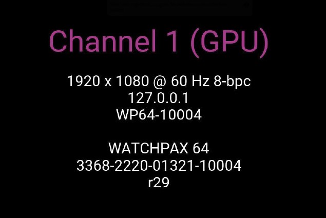
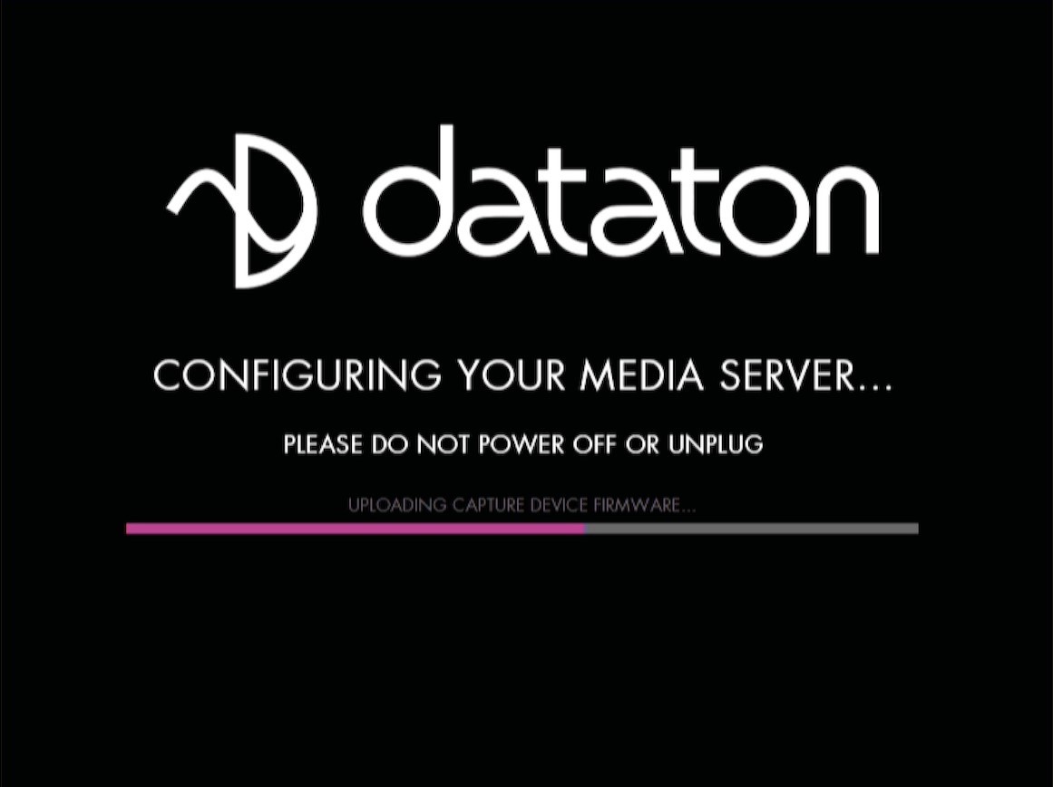
START UP SCREEN
IMPORTANT: The WATCHPAX 64 will always run WATCHOUT 7. It is not compatible with WATCHOUT 6.
This screen (Fig.2) is shown on all display devices connected to the WATCHPAX 64 at start-up.
ENVIRONMENTAL
Temperature range
- Optimal ambient temperature range for operation 21°C to 23°C
- Operating 0°C to +35°C
- Storage and transportation -20°C to +40°C
Relative humidity
- Optimal 45% to 50%
- Operating 20% to 85 % (non-condensing)
- Storage and transportation 10% to 90% (non-condensing)
Altitude
- Operating, maximum 2000 meters above sea level
MEDIA SERVER OPERATING SYSTEM
The operating system in WATCHPAX 64 has been optimized and licensed for this specific media server configuration.
NOTE: Do not install or attempt to install any software on the locked-down media server (such as drivers, software updates, security updates, virus protection, etc). Doing so will automatically void the unit’s warranty.
For better security, media servers are recommended to be installed and operate on a separate network, without access to other networks.
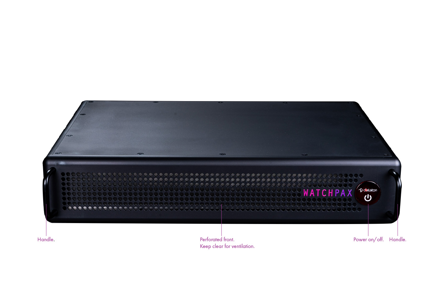
CONNECTORS
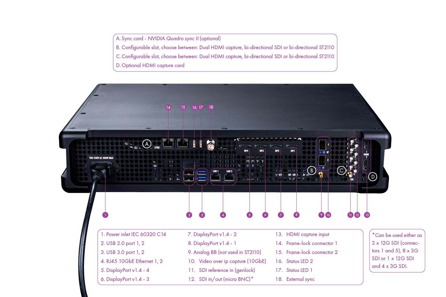
 >IMPORTANT: Do not connect a network from your switch, router or network jack to either of the RJ45 ports on the sync card (no. 14 & 15 in the picture above), as these ports are reserved for sync data only. The sync card will not operate if a network is connected to any of those ports.
INSTALLATION AND OPERATION
TABLE OF CONTENT
BEFORE USING YOUR WATCHPAX 64
Please read the manual thoroughly before operation. Always check that the unit has not been damaged in transit when you take delivery. >IMPORTANT: The WATCHPAX 64 is a plug-and-play unit. Do not open, modify or repair the unit yourself. Opening, modifying (software or hardware) or repairing the unit yourself willl invalidate the warranty and presents a risk for the user.
SAFETY FIRST
- Insert the power plug all the way in, so it is not loose.
- Do not place the power cord or product near heat sources.
- Caution: shock hazard if handled carelessly or inaccurately.
- The unit shall be connected to a grounded outlet.
- Do not use a damaged power cord or plug.
- Do not touch the power plug with wet hands.
- Do not install the product in a narrow space and/or where there is bad ventilation. Do not block the ventilation in any way when operated.
- Always keep plastic packaging away from children.
- Do not install the product on an unstable or vibrating surface.
- Install the unit in a clean, dry area without excessive particles or dust, in the air (preferably in an air-conditioned server room). Do not install the product in a place where it is exposed to high temperature, chemicals, dust, moisture, oil or smoke as this may seriously affect its performance and lifetime.
- Take care not to drop the product when moving it.
- When installing the product on a shelf, ensure the bottom edge of the product does not protrude to avoid tipping, for example.
- To move the product, first disconnect all the cables from it.
- The wall socket should be easily accessible for pluggable equipment.
- High voltage runs through the product. Do not attempt to disassemble, repair, or modify the product on your own.
- If the product generates a burning smell, or smoke, remove the power cords immediately and contact Dataton.
- If the product falls, or the exterior is damaged, power off the product, remove the power cords and contact Dataton.
- If there is a risk of thunderstorm or lightning strike, turn off the power and disconnect all cables.
- Do not insert a metallic object or inflammable object into any opening of the product.
- Unplug this product from the AC power supply before cleaning. Do not use liquid or aerosol cleaners on the product. Use a microfiber cloth for cleaning.
- After storage in cold conditions, let the product adapt to normal temperature for two hours before powering on.
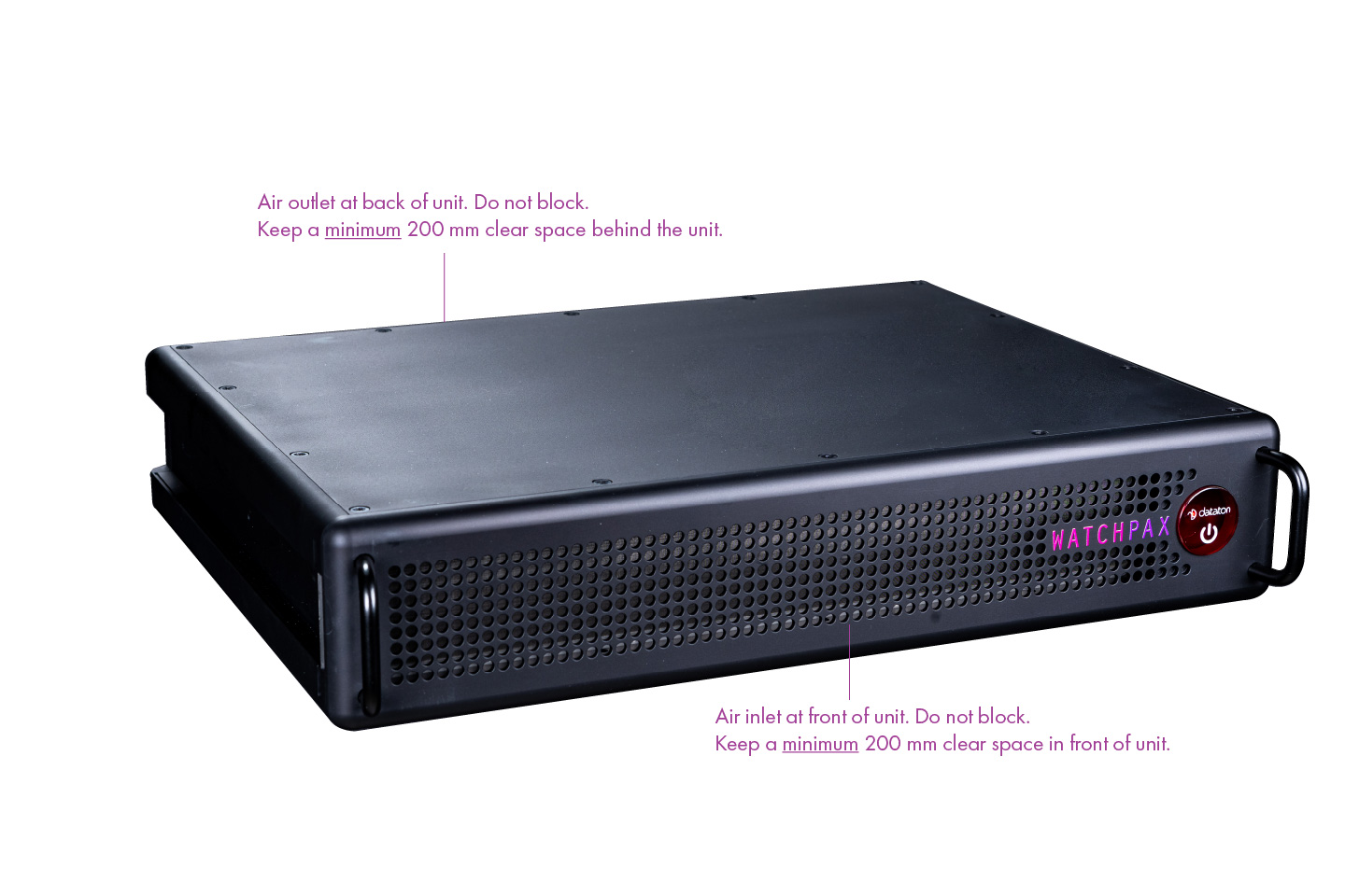
VENTILATION
Airflow is critical for the correct operation of WATCHPAX 64. Do not block front or back of the unit. In any installation, there should always be a minimum of 200 mm clear space at front and 200 mm behind the unit.
The air filter can be manually removed from the unit for cleaning purposes. Recommended method for cleaning the filter is with a vacuum cleaner and/or by rinsing it with warm water. Make sure the filter is dry before reinserting it into the WATCHPAX 64.
INSTALLATION
GENERAL
- This equipment is for professional use for installation at locations where only adults are normally present. Check the “Safety First” list before use.
- The WATCHOUT 64 must be connected to a properly grounded wall socket (a socket-outlet with protective earth connection in the building).
- The serial number is located on the base of the unit.
IMPORTANT: Only use the power cord supplied with the WATCHPAX 64 unit, otherwise Dataton AB cannot guarantee full functionality.
STANDALONE INSTALLATION
Place the unit flat with the base down. Mount the four self-adhesive rubber feet (supplied) at the points indigated on the base of the unit.
INSTALLATION IN 19-INCH RACK
The WATCHPAX 64 unit may be mounted in a 19-inch rack by using the optional rack kit. Please refer to separate instructions for rack assembly.
POWER ON
The WATCHPAX 64 unit is switched on by inserting the power cord or inserting the power cord and using the on/off switch. (see Connectors in the Introduction). Wake-on-LAN (WOL) may also be used with other units that support it.
FIRST POWER ON
The first time you power up a WATCHPAX 64 (after delivery or after a reset) the system will finalize installation and reboot several times. This procedure will typically take about 5 minutes to complete.
IMPORTANT: Do not interrupt this procedure.
POWER OFF
Powering down should be initiated from within WATCHOUT Producer software.
When the power-off sequence is complete, the fans will turn off, and the power cord may be removed.
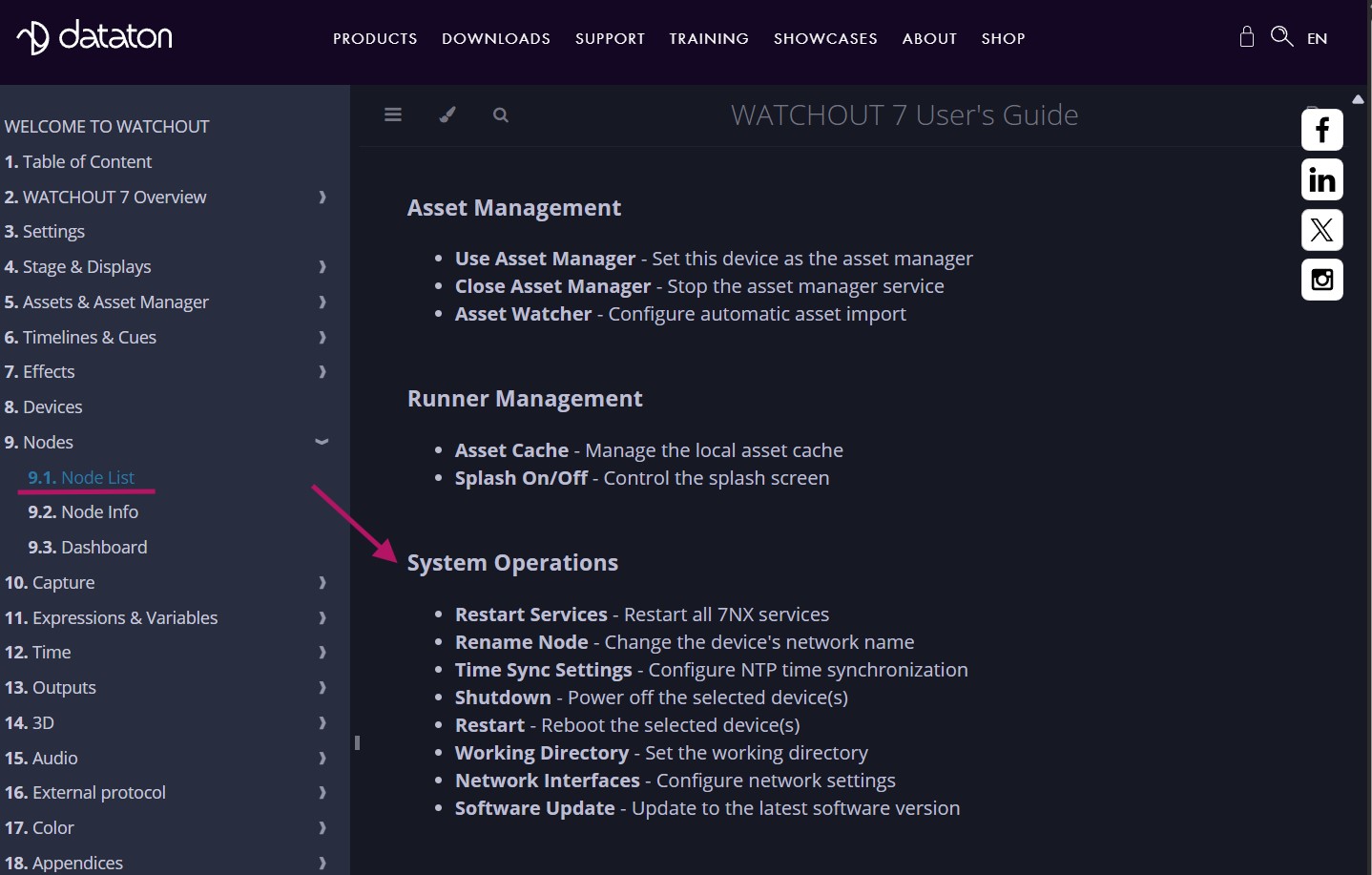
To power the unit down from within the WATCHOUT 7 Producer software, do the following: In the Nodes window, right click on your display device (the WATCHPAX 64 in this case) and select Shutdown. For more information, please refer to chapter 9.1: Node List in the "WATCHOUT 7 User's Guide".
It is also possible to power the unit down from WATCHPAX Config, a network-based UI.
NOTE: If you are unable to shut down via the software, you can force shutdown with the power button as a last resort. Please be aware that this may cause data loss and system corruption. To force shutdown in this way, press and hold the power button located on the front of the media server (see Connectors in the Introduction) for at least 5 seconds. The light will then turn off and the power is cut.
IMPORTANT: Do not unplug the power cord during power-off, as this may cause data loss and system corruption.
QUICK START
- Connect displays to the WATCHPAX 64 using the DisplayPort outputs.
- Connect the WATCHPAX 64 to the network using one of the Ethernet ports.
- Power on the WATCHPAX 64.
- Start the WATCHOUT Producer software on the production computer, which is on the same network. Make sure you are using WATCHOUT version 7.
RESET WATCHPAX 64
There are occasions when you may want to reset a WATCHPAX 64, for example, if the unit has been corrupted, or if it is a rental unit and user-specific info has to be removed between rentals. There are two levels of reset:
- Reset and keep user data. This resets the operating system, display, GPU and capture settings but retains user data, such as shows and media.
- Reset to factory settings. This takes the unit all the way back to the original factory settings and you lose all user data.
IMPORTANT: A reset, regardless of level, is an advanced measure. Make sure you are fully aware of what data you lose when you reset!
RESET AND KEEP USER DATA
This option resets the system partitions but keeps all user data such as:
- Shows
- Media
- WATCHOUT settings
- Startup script
- Network settings
- Timecode settings
Driver-related settings will be reset to default factory settings such as:
- Display settings
- Display mode
RESET TO FACTORY SETTINGS
This resets all partitions to factory settings and all user data will be lost. This level of reset is suitable when you want to remove all settings between projects.
RESET PROCEDURE
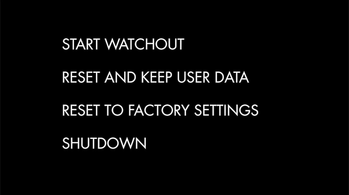
The reset menu is hidden by design in order to avoid accidental resets or misuse. To reset your WATCHPAX 64 device, follow these steps:
- Power off the WATCHPAX 64.
- Disconnect any USB devices.
- Now connect a keyboard to one of the USB ports.
- Connect at least one display device to a DisplayPort output.
- Power on the WATCHPAX 64.
- During startup, you will see a five-second countdown in the top left corner of the display. Press Esc during this countdown.

NOTE: If you don’t see a counter, it means the display device is slow to lock to the output. In that case, press Esc repeatedly after power-on to move to the menu below.
- Select the desired reset option in the menu that appears, and press Enter.
IMPORTANT: There will be no confirmation – the reset process starts immediately!
- As noted above, the reset process starts immediately, providing some visual feedback.
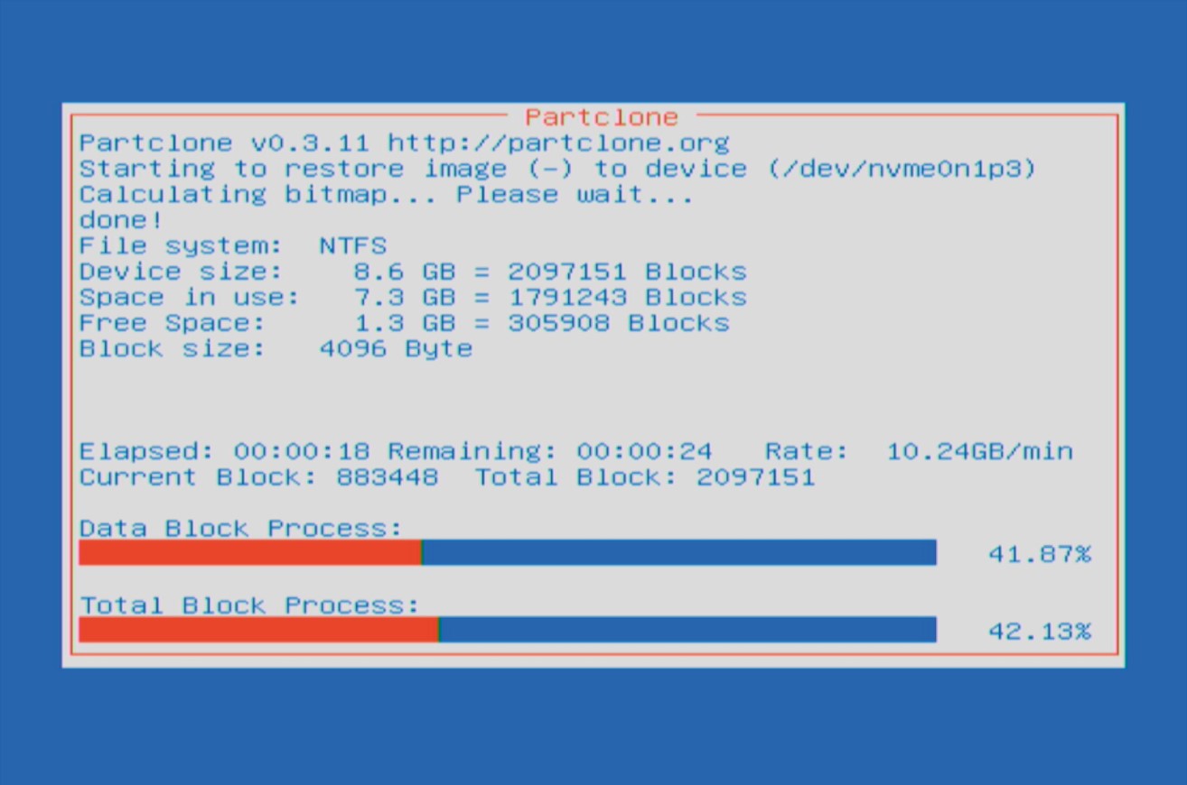
- The WATCHPAX 64 will restart several times in order to configure the operating system and hardware.

IMPORTANT: Do not power off the unit during the configuration process!
- WATCHOUT will start when the process is complete. The system image version will be appended after the serial number.
MISCELLANEOUS
AUDIO
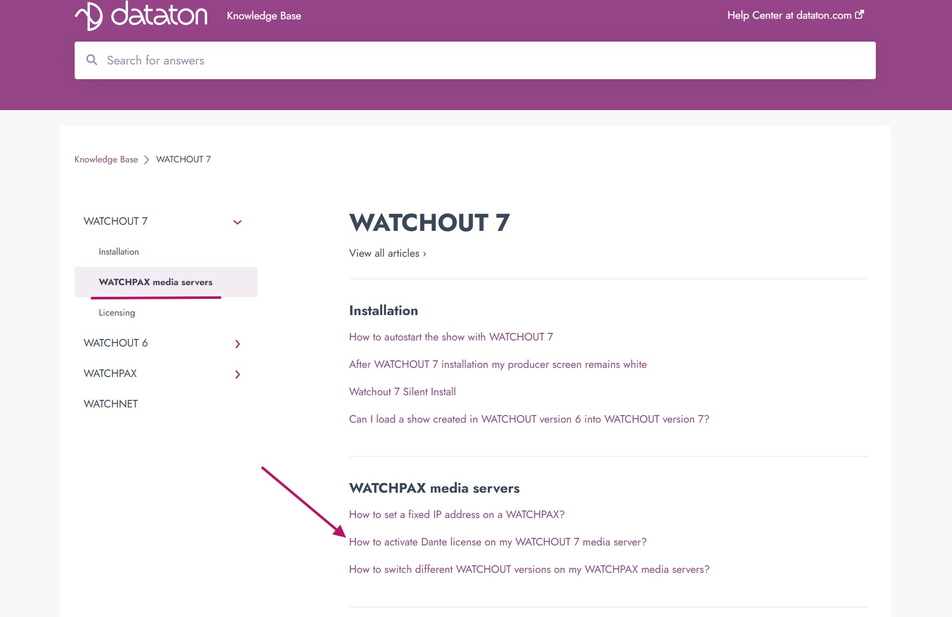
The WATCHPAX 64 is Dante® ready, meaning that a Dante® license can be purchased and activated on the unit, by the user. Instructions for this can be found in the knowledge base on the Dataton website.
Digital audio output formats:
WATCHPAX 64 can output multi-channel (7.1) LPCM audio embedded with DisplayPort and HDMI.
DIGITAL AUDIO OUTPUT RATES
- 44.1 kHz
- 48 kHz
- 88.2 kHz
- 96 kHz
- 176.4 kHz
- 192 kHz
WATCHPAX Config
WATCHPAX Config is a user interface that can be accessed and utilized through a web browser, so long as the WATCHPAX 64 and the computer running the Producer software are on the same network. To access the user interface, enter the ip address of the WATCHPAX 64, followed by ":3024" into the web browser's search bar (e.g. 192.168.5.64:3024).
In this user interface you can access different settings, such as mosaic configurations, EDID read/capture, the GPU topology and display configurations. For more info on how to set these features up, see the Synchronization chapter.
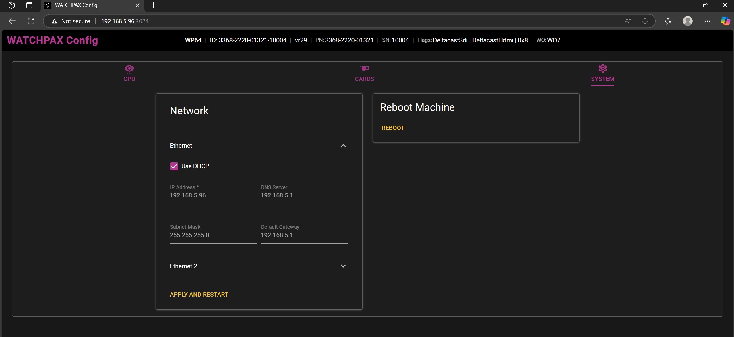
IP address settings can also be accessed from WATCHPAX Config, for setting of static IP addresses.
SYNCHRONIZATION
TABLE OF CONTENT
The WATCHPAX 64 can optionally be equipped with a NVIDIA Quadro Sync II card, which enables some useful functionalities. These include synchronizing mosaic groups spanning several GPUs, frame locking, synchronization to an external timing source as well as outputting an internal timing source.
Below are instructions on how to access these features from within the WATCHPAX Config network-based user interface.
ACCESSING WATCHPAX CONFIG
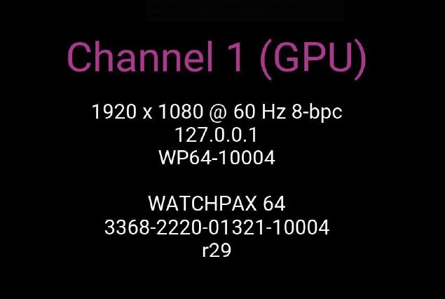
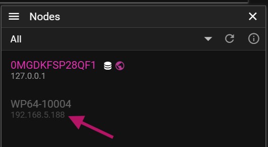
Start by finding the IP address of the WATCHPAX 64. It should show on the WATCHOUT splash screen, but if that is unavailable, the IP address can also be found in the Nodes window in the Producer software on the production computer. The WATCHPAX name will be displayed, with its IP address right below it.
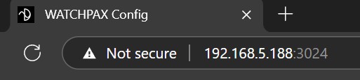
Open up a web browser and visit the server address with port 3024. The WATCHPAX 64 and the production computer both need to be on the same network for WATCHPAX Config to be accessed.
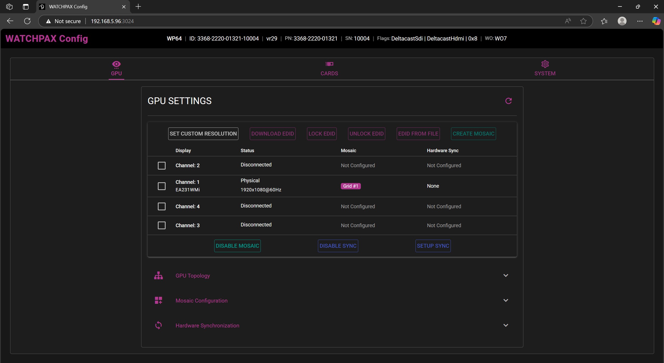
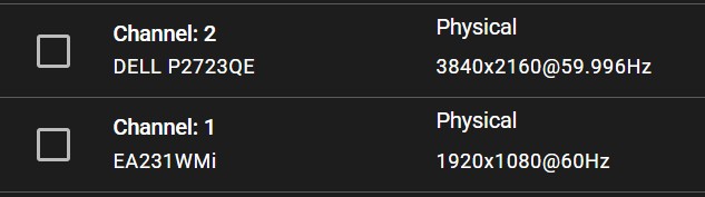
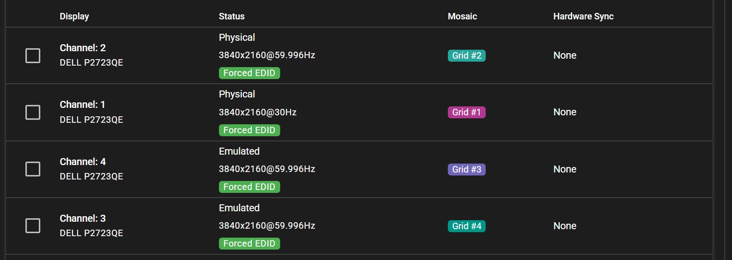
A user interface will be displayed, showing information about all connected outputs.
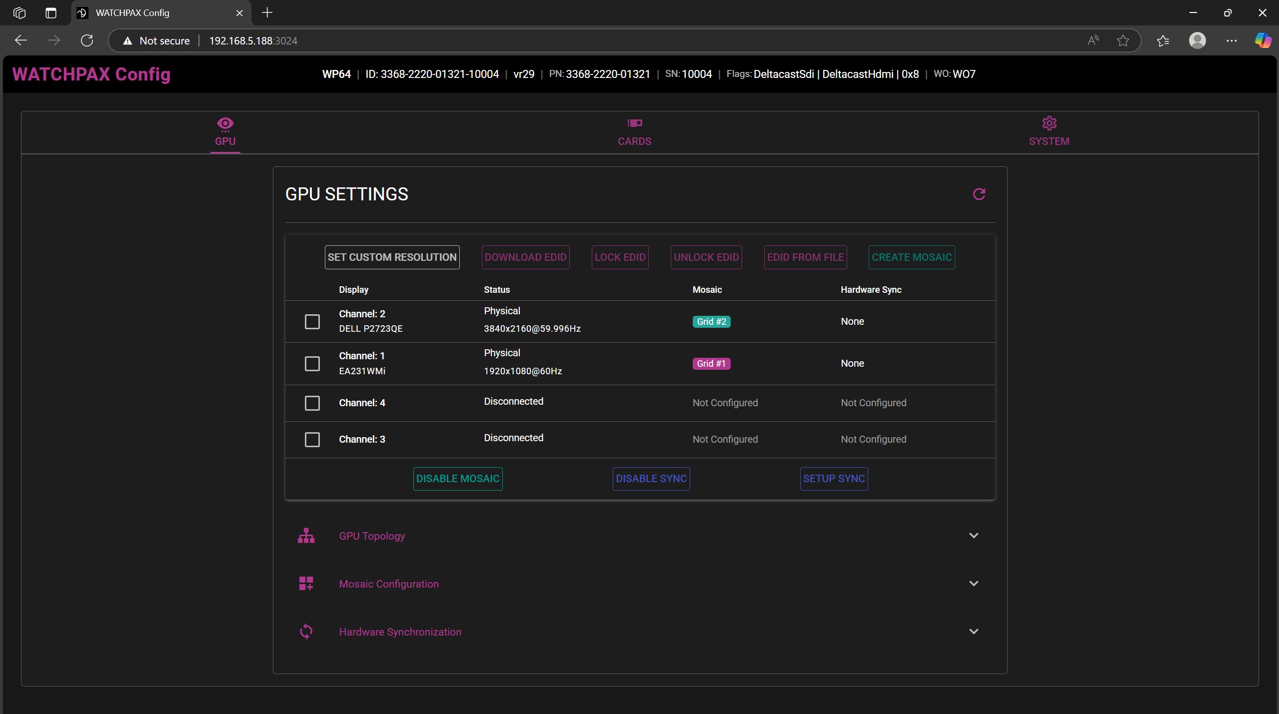
All channels should show a display connected under the 'Channel' label, as well as the current resolution and refresh rate.
NOTE: In the case of using mosaic clusters with several WATCHPAX units, each server must be set up separately.
IMPORTANT: Hardware synchronization functions will only work if the system is set up in the correct sequence, as below.
- EDID emulation needs to be handled first.
- Mosaic grid should follow.
- Hardware sync is the last one to be enabled.
SETTING UP EDID EMULATION
- Download the EDID from a display.
Select the display in the list and choose the Download EDID option.
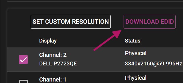
NOTE: The web browser may consider the downloaded file insecure and might require additional actions to approve it.
- Select all displays and choose EDID FROM FILE.
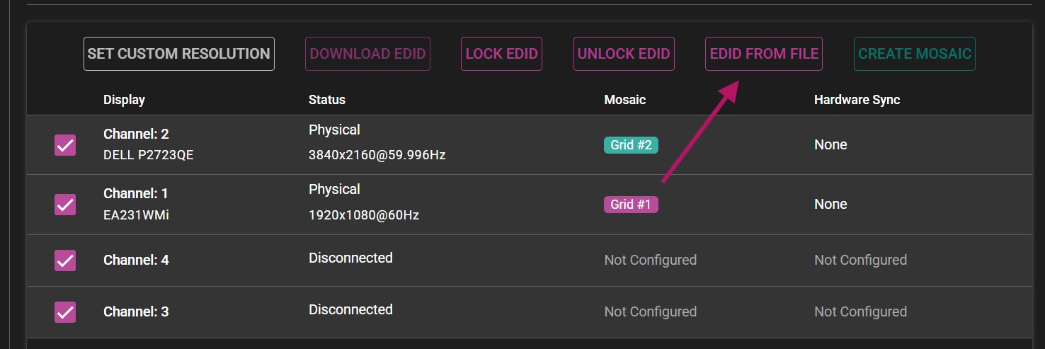
A new menu will appear, allowing you to upload the previously downloaded EDID to all display channels. Browse to the downloaded file.
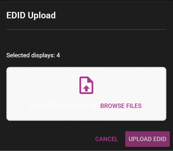
After uploaded the EDID, all channels should show the Forced EDID label under their status.
ENABLING MOSAIC
IMPORTANT Before beginning, make sure all displays have the ability to use a desired display mode (resolution + refresh rate)
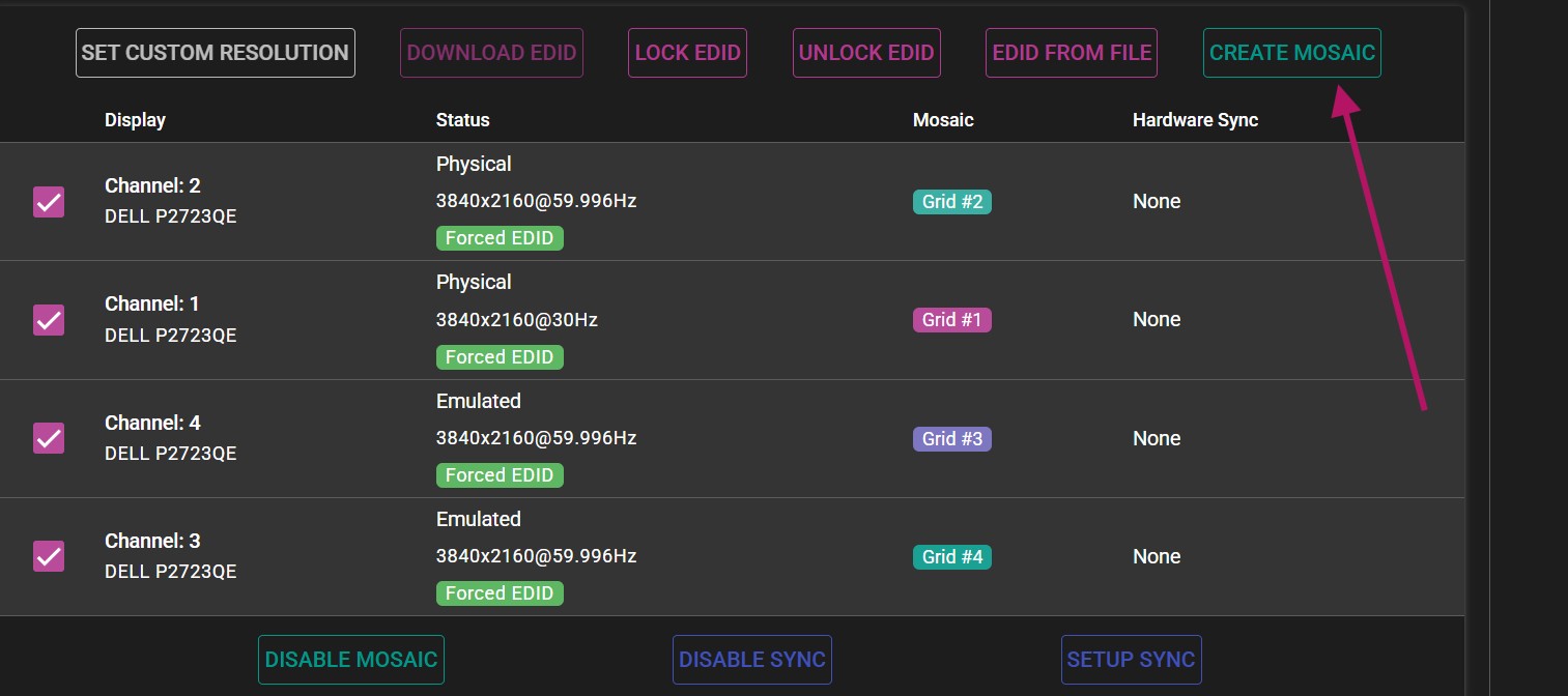
- Select all displays and select the CREATE MOSAIC option. If there is only one display present or only one display selected, the option will be grayed out.
- In the Create Mosaic Grid menu, configure the grid to specification.
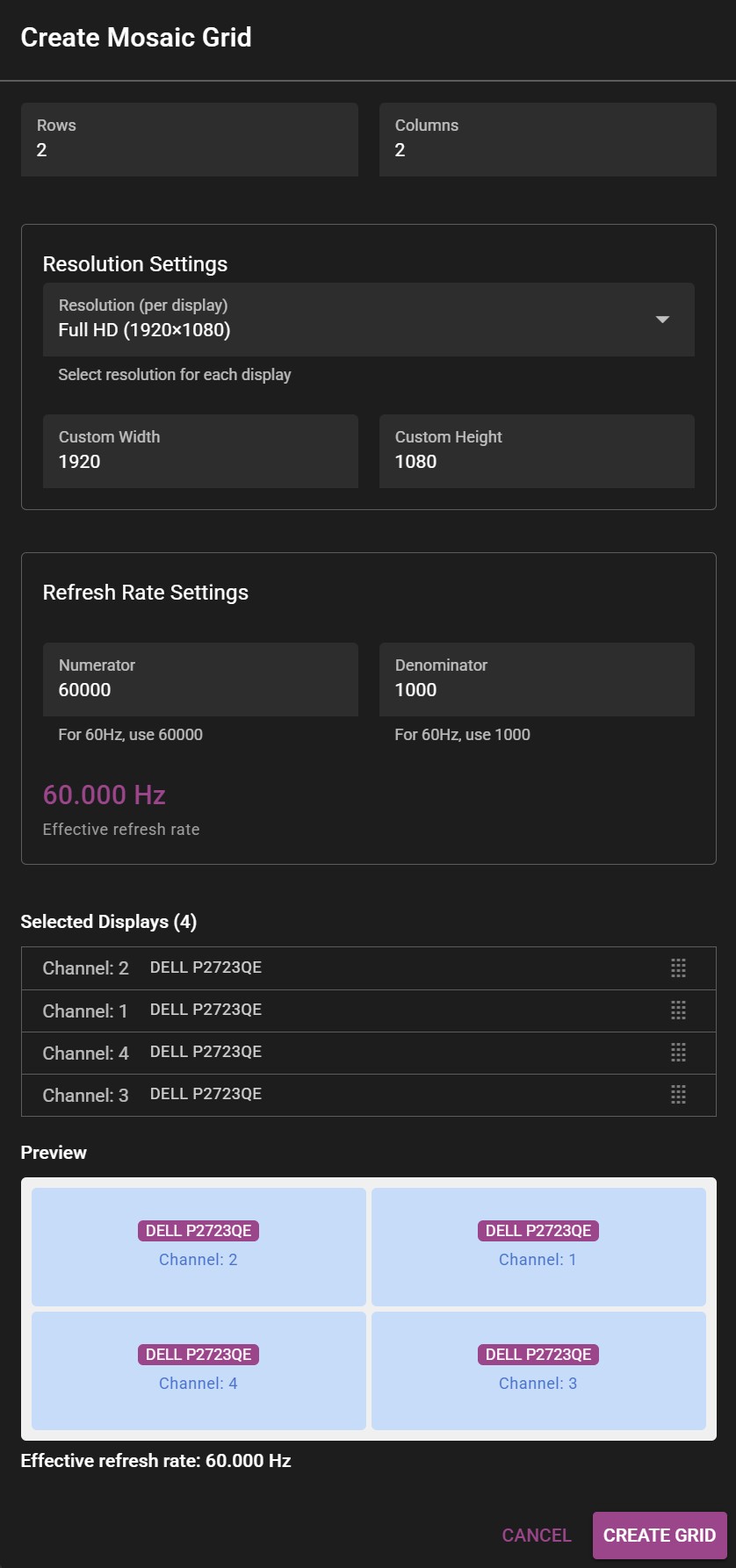 Example of the Create Mosaic Grid window.
-
Select the appropriate number of rows and columns. >For 2x2 setup, the number of columns and rows will be 2 each. >For 4 displays stacked horizontally (panorama), the grid would consist of 1 row and 4 columns (1x4).
-
Select the resolution (for each display) by specifying width and height. >The resolution is specified for each participating display, not the whole resulting mosaic. >For example: To get a 4K mosaic from 4 HD outputs, you would put 1920x1080 in Custom Width and Custom Height respectively.
-
Select desired refresh rate.
NOTE: For 59.94 Hz the correct values are 60000 for Numerator and 1001 for Denominator.
- Drag the correct channels to their respective positions in the preview panel to create the desired layout.
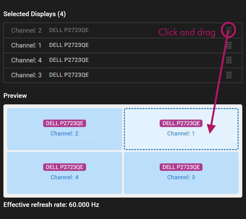
- Click Create Grid to apply changes.
NOTE: Before finalizing the mosaic grid, make sure WATCHOUT is not rendering on the displays that are being used for the grid. Disable all of them before accepting changes.
- If everything was set up correctly, a message will confirm that the mosaic grid was created successfully.

HARDWARE SYNC
PHYSICAL SETUP
Before configuring the sync settings, make sure the servers are correctly connected together.
- Use CAT6 or better ethernet cables.
- Status LEDs on Quadro Sync cards should be active (either orange or green color).
- Cable length should be short and of high signal integrity.
- Do not make signal loops. This is a linear chain.
- It is possible to use either of the two ethernet ports on the card when connecting the units with a cable.
The sync signal should be structured in the following manner, with the signal source in the middle of the cluster:
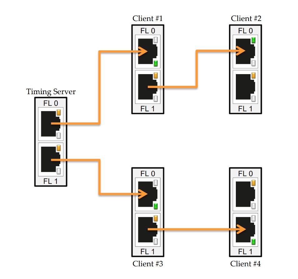
This way, the distance that the signal needs to travel is cut down, which provides a more stable signal.
- Use the SETUP SYNC option to create the hardware sync settings.
NOTE: Set up the machine that includes the timing server first. Only one output on one server can become the timing source, all other outputs should be set up as clients.
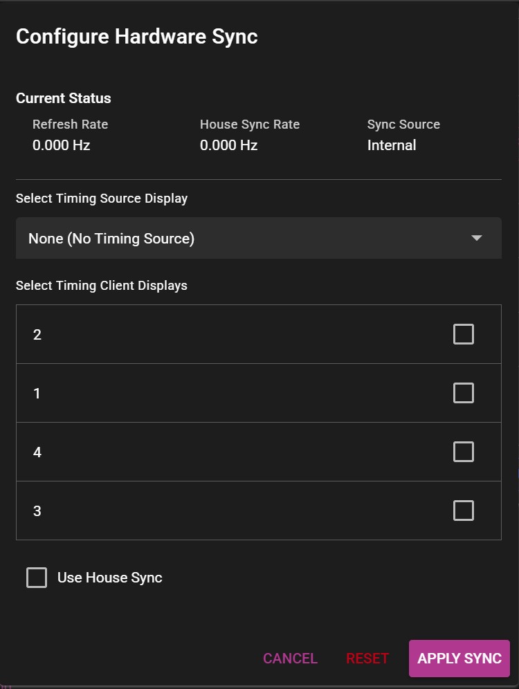 Example of the Configure Hardware Sync window.
-
On the server that will serve as the signal source, select the timing source display. Skip this step on the rest of the servers.
-
Select all remaining displays as clients.
-
Click Apply sync and wait for a confirmation message.

Typical setup for 4 display servers:
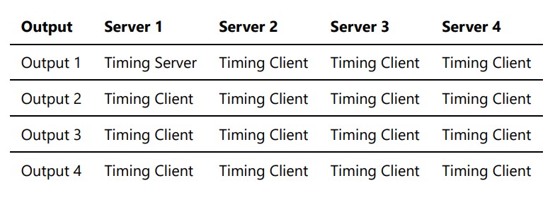
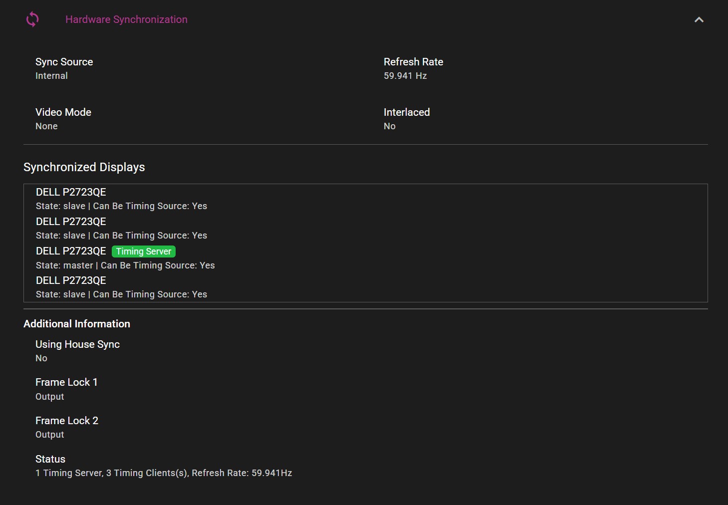
Current sync configuration can be viewed in the Hardware Synchronization section:
WARRANTY, CONFORMITY AND DISPOSAL
TABLE OF CONTENT
LIMITED WARRANTY
DATATON AB (”Dataton”) DATATON AB (”Dataton”) warrants this hardware product against defects in materials and workmanship for a period of seven hundred and thirty (730) days from the date of original retail purchase.
If you discover a defect, Dataton will, at its option, repair, replace, or refund the purchase price of this product at no charge to you, provided you return it during the warranty period, in the original packaging, transportation charges pre-paid, to the authorized Dataton vendor from whom you purchased it, any other authorized Dataton sales point in the country of the original retail purchase or to Dataton itself. More information is available from Dataton AB, see address.
When returning an item, you are advised to first contact the vendor or Dataton. You should then fill in the RMA (Return Merchandise Authorization) form available on www.dataton.com stating your name, address, contact details, a description of the problem, serial numbers and point of purchase. Dataton also requires a copy of the bill of sale or packing list bearing the appropriate Dataton serial numbers (where applicable) as proof of the date of original retail purchase.
This warranty applies only to hardware products manufactured by Dataton AB which are labeled with the Dataton logo and returned in the original packaging. This warranty does not apply if the product has been damaged by accident, abuse, misuse or misapplication, nor if the product has been opened or modified without the written permission of Dataton, nor if any serial number has been removed or defaced.
All implied warranties, including implied warranties of merchantability and fitness for a particular purpose, are limited in duration to seven hundred and thirty (730) days from the date of original retail purchase of this product. The warranty and remedies set forth above are exclusive and in lieu of all others, oral, written, express or implied.
No Dataton dealer, agent or employee is authorized to make any modification, extension or addition to this warranty (see note on extended warranty below).
Dataton is not responsible for special, incidental or consequential damages resulting from any breach of warranty, or under any legal theory, including lost profits, downtime, goodwill, damage to or replacement of equipment and property, and any costs of recovering, reprogramming or reproducing any program or data stored in or used with Dataton products.
If extended warranty terms have been agreed with Dataton at purchase, proof shall be presented.
Dataton AB • Teknikringen 22 • SE 583 30 LINKÖPING • Sweden
Email: [email protected]
DECLARATION OF CONFORMITY
Product name: WATCHPAX 64
Model number: 3368
Description: Media server
Responsible manufacturer: Dataton AB
Address: Teknikringen 22, SE-583 30 Linköping, Sweden
Dataton AB hereby declares that the product listed above, to which this Declaration of Conformity relates, complies with the standards and regulations below:
FCC – Complies with
-
FCC Regulations Title 47 Chapter 1, Part 15, subpart B, Class A:
§15.107: Conducted Emission, AC power line
§15.109: Radiated Emission
CE – Complies with
EMC Directive 2014/30/EU
-
Emission according to EN 55032:2015, Class A, +A11:2020
Electromagnetic compatibility of multimedia equipment
-
Emission according to EN 61000-3-2:2014
Limits for harmonic current emissions (equipment input current > 16 A per phase)
-
Emission according to EN 61000-3-3:2013
Limitation of voltage changes, voltage fluctuations and flicker in public low-voltage supply systems Immunity according to EN 55035:2017, Edition 2 Immunity characteristics - Information technology equipment
Low Voltage Directive 2014/35/EU
-
EN 62368-1:2014
Audio/video, information and communication technology equipment - Part 1: Safety requirements
RoHS Directive 2011/65/EU
-
EN IEC 63000:2018
Technical documentation for the assessment of electrical and electronic products with respect to the restriction of hazardous substances
WEEE – Complies with
-
Directive 2012/19/EU
Waste from electrical and electronic equipment
Linköping, May, 2024
Björn Sandlund - Founder and owner
DISPOSAL
Only for European Union and EEA (Norway, Iceland and Liechtenstein)
This symbol indicates that this product is not to be disposed of with your household waste, according to the WEEE Directive (2012/19/EU), the Battery Directive (2006/66/EC) and/or national legislation implementing those Directives. If a chemical symbol is printed beneath the symbol shown above, in accordance with the Battery Directive, this indicates that a heavy metal (Hg = Mercury, Cd = Cadmium, Pb = Lead) is present in this battery or accumulator at a concentration above an applicable threshold specified in the Battery Directive.
This product should be handed over to a designated collection point, e.g., on an authorized one-for-one basis when you buy a new similar product or to an authorized collection site for recycling waste electrical and electronic equipment (EEE) and batteries and accumulators. Improper handling of this type of waste could have a possible impact on the environment and human health due to potentially hazardous substances that are generally associated with EEE. Your cooperation in the correct disposal of this product will contribute to the effective usage of natural resources.
For more information about the recycling of this product, please contact your local city office, waste authority, approved scheme or your household waste disposal.